PDT magnifier camera illumination

a magnifier camera and magnifier technology, applied in the field of magnifier camera illumination, can solve the problems of remained problematic uniform, symmetrical illumination of objects being viewed, and troublesome use of magnifying glass to enlarge prints, so as to achieve the effect of minimizing light leakag

Active Publication Date: 2011-03-15
FREEDOM SCI
View PDF11 Cites 0 Cited by
  • Summary
  • Abstract
  • Description
  • Claims
  • Application Information

AI Technical Summary

Benefits of technology

[0017]An important advantage of the invention is that the object being viewed is illuminated in an optimal way by the light emitting diodes (LEDs) that are strategically positioned about the perimeter of the optical light guide lens. The optical light guide lens has a specific structure that bends light rays emitted by the LEDs into the object being scanned without any reflections of the LEDs on the camera.
[0018]Another major advantage is that the novel structure minimizes light leakage about the periphery of the optical light guide lens.
[0019]These and other advantages will become apparent as this disclosure proceeds. The invention includes the features of construction, arrangement of parts, and combination of elements set forth herein, and the scope of the invention is set forth in the claims appended hereto.

Problems solved by technology

Using a magnifying glass to enlarge print is problematic.
Uniform, symmetrical illumination of the object being viewed has remained problematic.

Method used


Image

  • PDT magnifier camera illumination
  • PDT magnifier camera illumination
  • PDT magnifier camera illumination

Examples


Embodiment Construction

[0029]U.S. patent application Ser. No. 11 / 308,298, entitled “Magnifier Having Slideably Mounted Camera,” filed by the same inventors on Mar. 15, 2006, which application claims priority to U.S. provisional patent application No. 60 / 595,003, entitled: “Portable Electronic Magnifier,” filed by the same inventors on May 26, 2005, is hereby incorporated by reference into this disclosure.

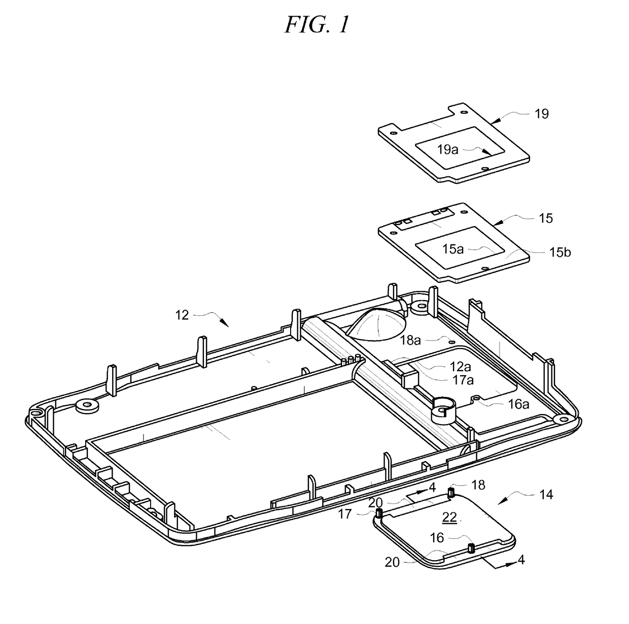
[0030]FIG. 1 of the present disclosure depicts bottom housing 12 that is engaged at its periphery by sidewalls 14a, 14b, 14c, and 14d of top housing 10 depicted in FIGS. 2, 3 and 4 of the incorporated disclosure. Generally rectangular opening 12a is formed in said bottom housing 12 at a first end thereof so that when bottom housing 12 is attached to top housing 10 of the incorporated structure, opening 12a is in registration with mirror 26 of the structure depicted in the incorporated disclosure. Thus, rectangular opening 12a is understood to be a camera aperture. The user of the device slides opening 12a...


PUM


Abstract

A device that enlarges text and images to enable a low vision person to see the text and images includes a hollow structure including a top housing and a bottom housing that are connected to one another. A camera aperture is formed in the bottom housing and a transparent light guide lens is disposed in closing relation to the camera aperture so that all light entering the camera aperture must first pass through the light guide lens. A cavity formed in the light guide lens is bounded by walls that are positioned at a critical angle. Light-emitting diodes are positioned at critical locations about the periphery of the light guide lens to illuminate the object being viewed.

Description

CROSS-REFERENCE TO RELATED DISCLOSURES[0001]This disclosure is a continuation of U.S. provisional patent application filed Mar. 21, 2006, Ser. No. 60 / 767,353, entitled: “Camera Magnifier Illumination,” by the same inventors, and which is incorporated by reference into this disclosure.BACKGROUND OF THE INVENTION[0002]1. Field of the Invention[0003]This invention relates, generally, to devices that enable people having low vision to read printed documents. More particularly, it relates to a camera in an electronic magnifier requiring symmetrical illumination when used in contact with or near a target object such as a printed document.[0004]2. Description of the Prior Art[0005]Using a magnifying glass to enlarge print is problematic. The glass must be positioned a specific distance from the paper to obtain optimal magnification, and the paper must be well-illuminated.[0006]The art has therefore moved in the direction of using video cameras to view the print and to drive a liquid crysta...

Claims


Application Information

Patent Timeline
Patent Type & Authority Patents(United States)
IPC IPC(8): F21V7/04
CPCG03B15/03
Inventor HANNEY, MIKEIEZZI, PETERCONARD, TODD
Owner FREEDOM SCI
Why Eureka
Try Eureka