Pixel interleaving configurations for use in high definition electronic sign displays

a technology of electronic sign display and interleaving configuration, which is applied in the field of electronic sign display, can solve the problems of increased led density, high cost and energy consumption, and increased led density for high definition resolution use, and achieves the effects of high image and color quality, reduced led density, and high definition capabilities

Active Publication Date: 2011-03-15
DAKTRONICS
View PDF48 Cites 47 Cited by
  • Summary
  • Abstract
  • Description
  • Claims
  • Application Information

AI Technical Summary

Benefits of technology

[0010]3. The LED spacing within an individual LED (red, green, blue) style pixel or spacing from pixel-to-pixel can be flexible. Spacing of the LEDs may be compacted within the pixel to ease manufacturing and, as such, pixel boundaries can easily be visually seen and identified), or uniform spacing can be used to create an even fill-factor across the LED sign where the pixel boundaries blend together, preferably making it difficult to visually identify which individual LEDs belong with which pixel.
[0015]Still another significant aspect and feature of the present invention is the reduction in the number of LEDs required in an electronic sign display by the use of interleaving of pixels while still maintaining a balanced and full red, green, and blue color representation in each scan row, often referred to as full color rows of resolution.
[0017]A further significant aspect and feature of the present invention is the use of full color row resolution which does not experience color shift, which upholds high image and color quality, and which maintains high definition capabilities.
[0018]A still further significant aspect and feature of the present invention is that full color pixel content is provided for even use of the LEDs, whereby all LEDs age at an even rate.
[0020]A further significant aspect and feature of the present invention prevents side angle color shift that occurs when LEDs are packed very closely together.

Problems solved by technology

LEDs are a very significant percentage of the cost of an LED screen, and therefore, a screen with 720 pixels high by some arbitrary number of pixels wide can be extremely expensive and, therefore, cost prohibitive for many users.
Such an increase in the number of LEDs required for high definition resolution use can be problematic in terms of LED cost and in terms of energy usage.
Size limitations are also a cause of concern.
The physical size of these lamps along with the requirement to have at least three LEDs (red, green, and blue) limits how tightly the spacing can be between full color pixel elements.

Method used


Image

  • Pixel interleaving configurations for use in high definition electronic sign displays
  • Pixel interleaving configurations for use in high definition electronic sign displays
  • Pixel interleaving configurations for use in high definition electronic sign displays

Examples


Embodiment Construction

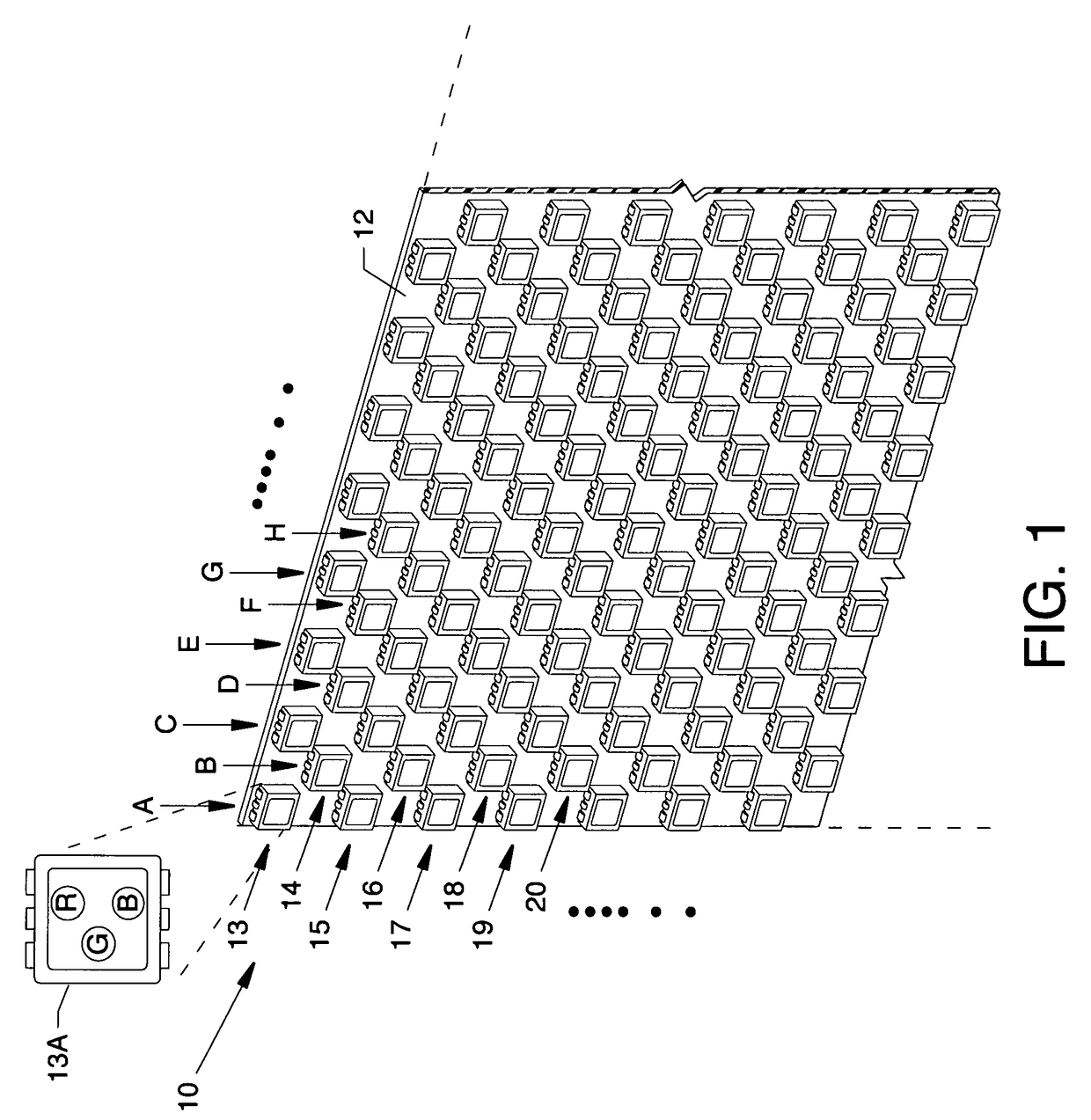
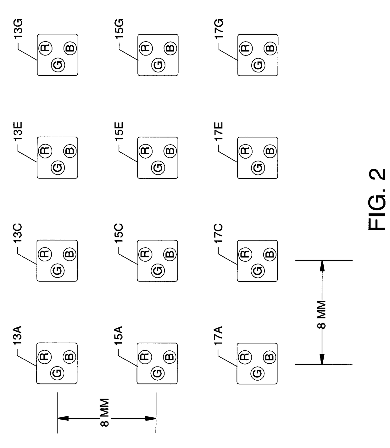
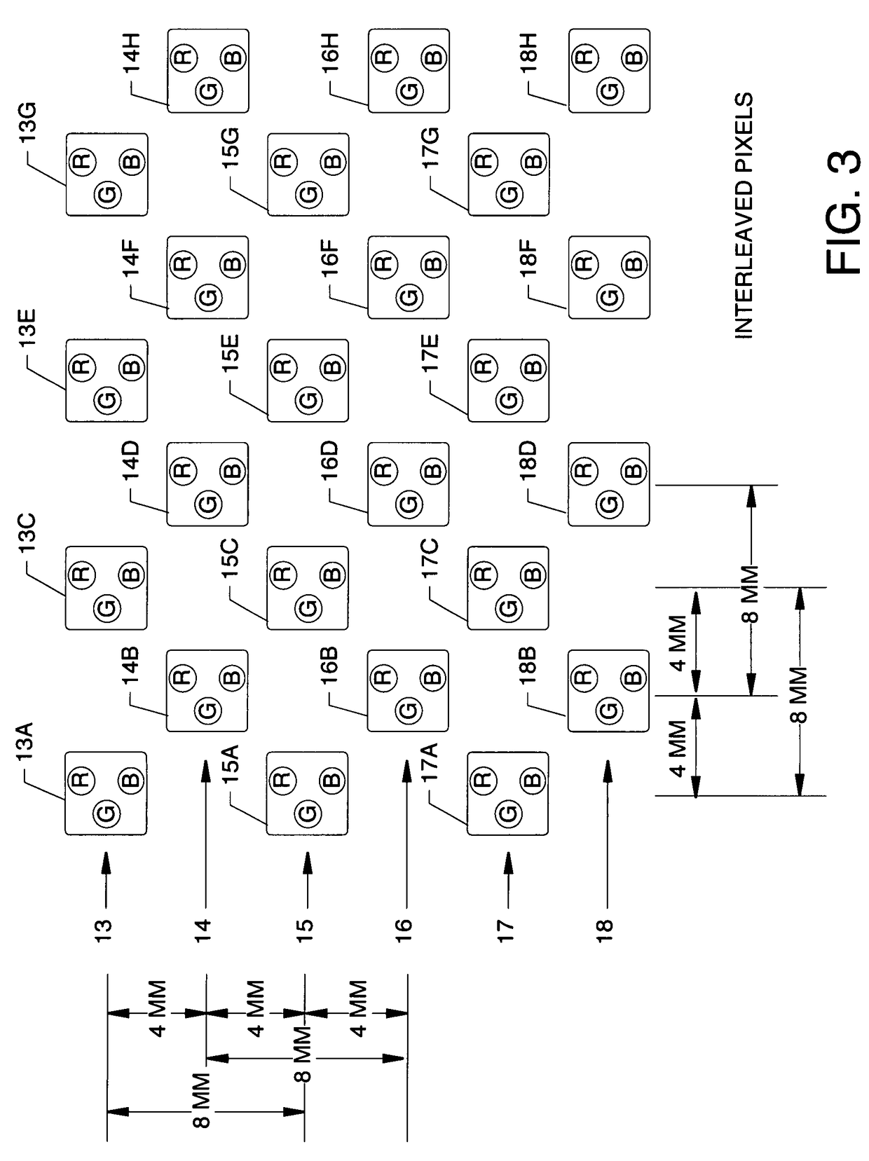
[0030]FIG. 1 is a segmented view showing a pixel interleaving configuration 10 for use in high definition electronic sign displays where a plurality of LED packages are arranged and mounted on a circuit board 12 which can be part of a high definition electronic sign display. The LED packages, each of which are a pixel, are arranged in alternating style having odd numbered rows 13, 15, 17, 19, and so on, alternating with even numbered rows 14, 16, 18, 20, and so on, where the even numbered rows 14, 16, 18, 20, and so on, are offset from the odd numbered rows 13, 15, 17, 19, and so on. Correspondingly, the LED packages are arranged in alternating style having columns A, C, E and G, and so on, alternating with columns B, D, F, H, and so on, where the columns B, D, F and H are offset from the columns A, C, E and G, and so on. The LED packages can be identified according to row and column. For example, the upper left LED package would be LED package 13A, the LED package beneath would be ...


PUM


Abstract

Pixel interleaving configurations for use in high definition electronic sign displays where each and every scan line includes full red, green, and blue color representation to provide for high resolution electronic video sign displays.

Description

CROSS REFERENCES TO RELATED APPLICATIONS[0001]This patent application is related to patent application Ser. No. 11 / 642,221 filed on Dec. 20, 2006, entitled “LED Display Module”, which is pending, and which is a continuation of patent application Ser. No. 11 / 271,404 filed Nov. 10, 2005, entitled “Modular Display System”, which is pending.[0002]This application claims priority from the earlier filed U.S. Provisional Application No. 60 / 791,808 filed Apr. 12, 2006, entitled “Interleaved Pixel Concept SMD-Style LEDs”. The prior application is hereby incorporated into this application by reference as if fully set forth herein.BACKGROUND OF THE INVENTION[0003]1. Field of the Invention[0004]The present invention to electronic sign displays and, more particularly relates to pixel interleaving configurations for use in high definition electronic sign displays.[0005]2. Description of the Prior Art[0006]Prior art electronic sign displays have often incorporated a plurality of light emitting dio...

Claims


Application Information

Patent Timeline
Patent Type & Authority Patents(United States)
IPC IPC(8): G06F3/038
CPCG09G3/2003G09G3/32G09F9/3026G09G2300/0452G09G2310/0224G09G2340/0407G09G2340/0428G09G2340/0457
Inventor JOFFER, BRENT A.WENDLER, BRETT D.LUKE, GLENN P.NEARMAN, NATHAN L.GLOEGE, CHAD N.MUELLER, MATT R.MUTSCHELKNAUS, SHANNON LEESCHULTE, JOSEPH G.BRAVEK, ERIC S.HANSEN, RYAN M.
Owner DAKTRONICS
Why Eureka
Try Eureka