Automated pace-mapping for identification of cardiac arrhythmic conductive pathways and foci

a technology of conductive pathways and foci, applied in the field of diagnosis and treatment of cardiac arrhythmias, can solve the problems of long time period, unstable ventricular tachycardia (vt), and patients who cannot tolerate mapping procedures, and achieve the effect of accurate activation map

Active Publication Date: 2011-03-15
BIOSENSE WEBSTER INC
View PDF25 Cites 76 Cited by
  • Summary
  • Abstract
  • Description
  • Claims
  • Application Information

AI Technical Summary

Problems solved by technology

One drawback with mapping a cardiac chamber using a catheter containing only a single, distal tip electrode is the long period of time required to accumulate data on a point-by-point basis over the requisite number of points required for a detailed map of the chamber as a whole.
Hence, patients with unstable ventricular tachycardia (VT) can not tolerate a mapping procedure that lasts long enough to produce an accurate activation map.
Currently, identification of such foci using the aforementioned mapping techniques is a long and tedious procedure, for example, involving visual comparisons between the complexes associated with clinical ventricular tachycardia and pace-mapped signals.
The VT-related patterns that are induced by electrophysiological pacing may be transient and difficult to identify.
As a result, the job of searching for VT foci can be tedious and inaccurate, and it may be too difficult for less experienced cardiologists.

Method used


Image

  • Automated pace-mapping for identification of cardiac arrhythmic conductive pathways and foci
  • Automated pace-mapping for identification of cardiac arrhythmic conductive pathways and foci
  • Automated pace-mapping for identification of cardiac arrhythmic conductive pathways and foci

Examples


embodiment 1

Alternate Embodiment 1

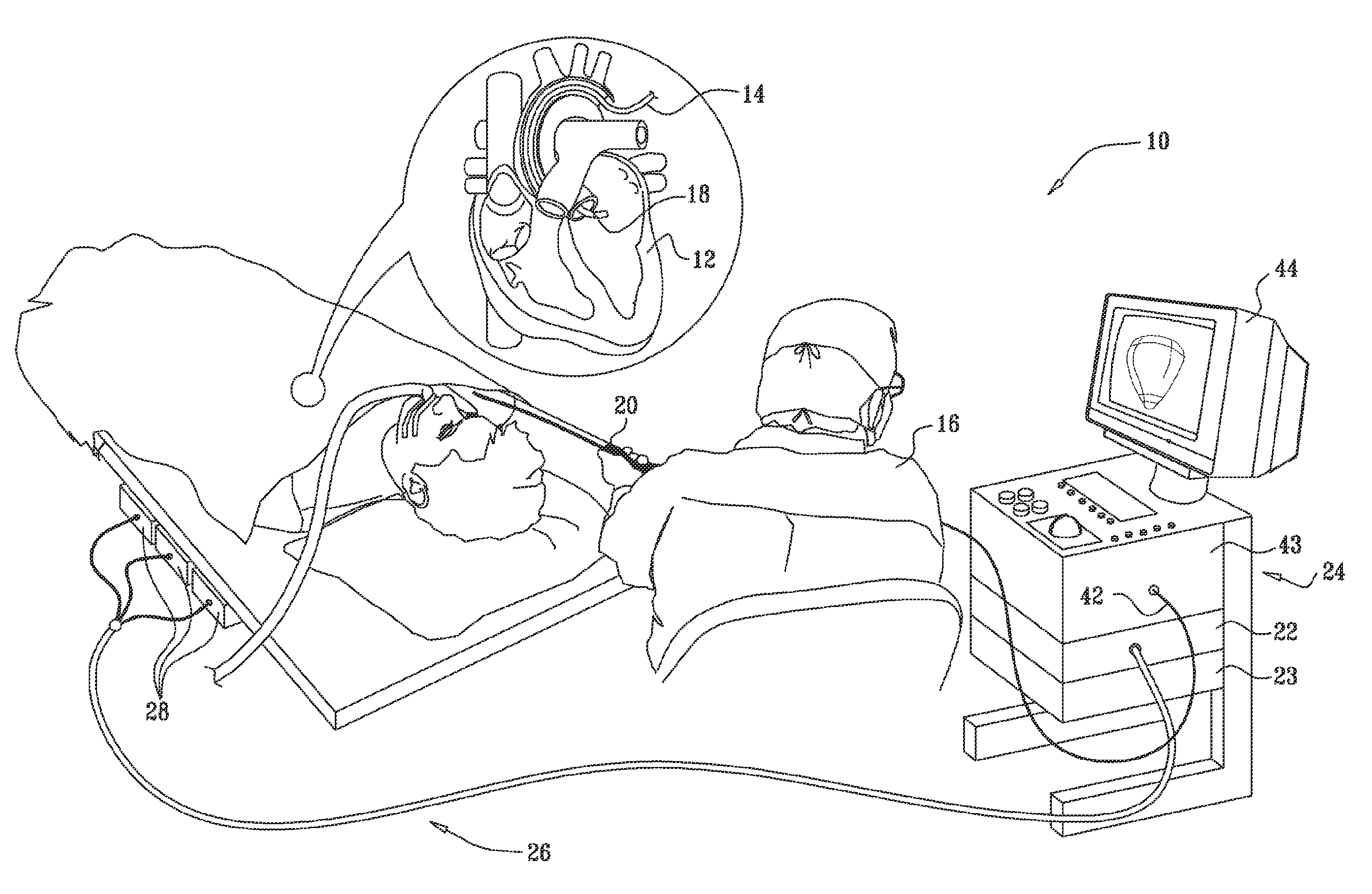
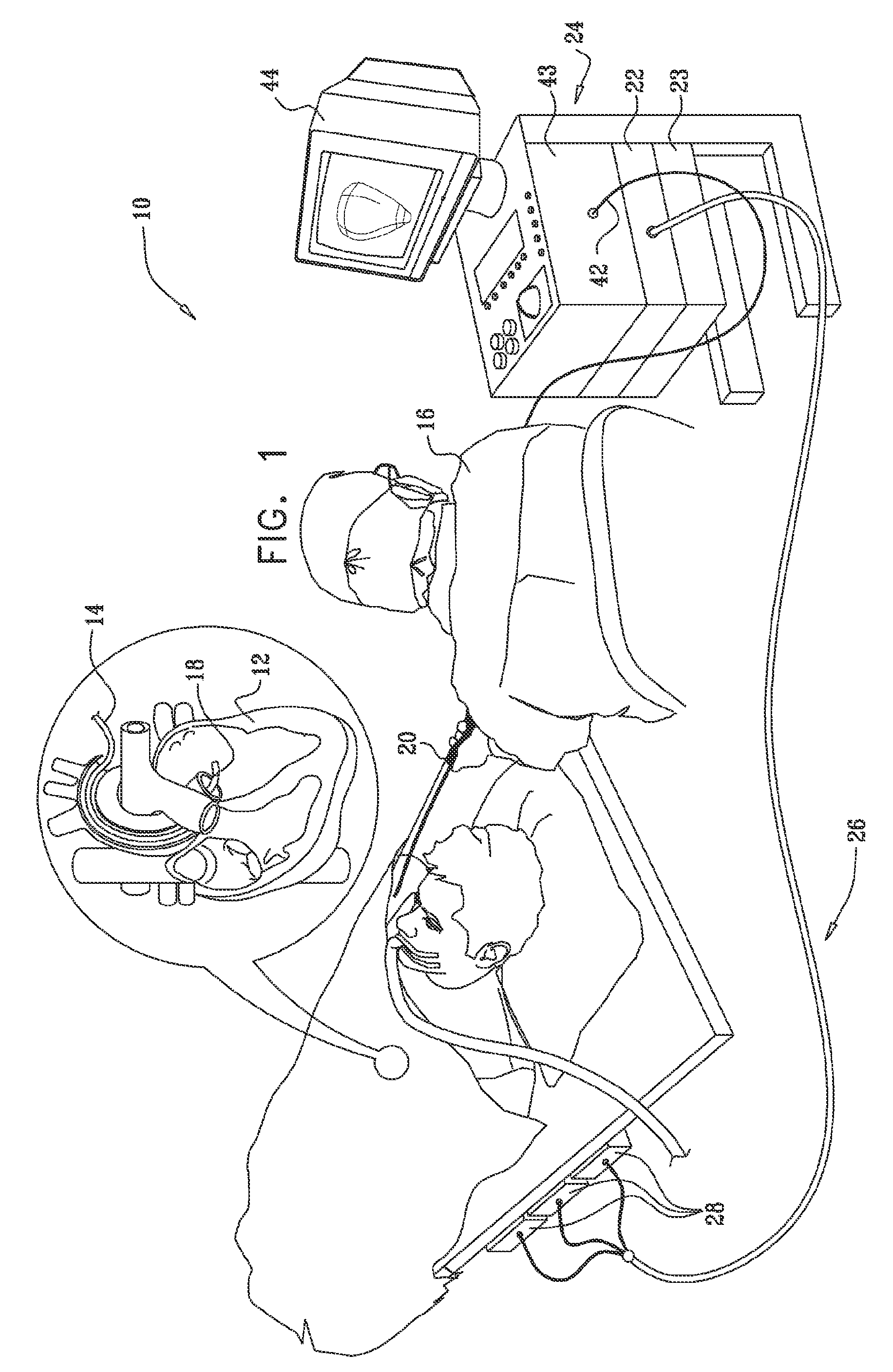
[0128]Referring again to FIG. 1, in this embodiment a cardiologist paces the heart at different locations in the ventricle while observing a 12-lead body-surface ECG, as described above. Upon observing a suspicious pattern in the ECG (containing tachycardia or other arrhythmic components), the cardiologist signals the system 10 to mark the time interval containing the suspicious pattern as well as the pacing location at which the pattern occurred. Multiple intervals may be marked in this manner. The system 10 then learns the characteristics of the suspicious ECG pattern.

[0129]Subsequently, the cardiologist scans the pacing catheter over the inner wall of the ventricle, while the system 10 monitors and analyzes the ECG signals to detect further occurrences of the pattern it has learned. The system 10 marks any locations at which the pattern recurs as possible VT foci. The cardiologist may then ablate these foci or conduct further studies around the focal locatio...

embodiment 2

Alternate Embodiment 2

[0152]In this embodiment, instead of using a conventional body surface electrocardiogram, electrocardiographic signals are captured using remote interrogation of implanted patient devices, typically intracardiac devices (ICDs) such as defibrillators, cardioverters, and pacemakers. Such devices may be provided with memories for storing signals that reflect cardiac events. Historic signals are downloaded as recorded (historic) signals or in realtime to a processing system and compared with induced signal patterns (a first type of realtime signal) and with pace mapped patterns (a second type of realtime signal). The historic signals may include spontaneous episodes of ventricular tachycardia. In some embodiments, the signals may be transmitted to and stored on a server and then transferred to the processing system. A suitable intracardiac device for capturing the signals is the Medtronic InSync® ICD. Other suitable devices are commercially available.

[0153]Referenc...


PUM


Abstract

Ventricular tachycardia signals are induced in a living subject. Pace-mapped signals are then obtained from multiple points within the ventricle, and automatically compared numerically with the induced signals. Recognition of a high degree of cross correlation between the induced signals and one or more of the pace-mapped signals identifies arrhythmogenic foci or pathways, which may then be ablated, so that the arrhythmia becomes non-inducible.

Description

CROSS-REFERENCE TO RELATED APPLICATIONS[0001]This application claims the benefit of U.S. Provisional Application No. 60 / 884,493 filed Jan. 11, 2007, which is herein incorporated by reference.BACKGROUND OF THE INVENTION[0002]1. Field of the Invention[0003]This invention relates to the diagnosis and treatment of cardiac arrhythmias. More particularly, this invention relates to the identification of arrhythmogenic foci associated with ventricular tachycardia.[0004]2. Description of the Related Art[0005]TABLE 1Acronyms and AbbreviationsDACDigital-To-Analog ConverterECGElectrocardiogramEEGElectroencephalogramFFTFast Fourier TransformICAIndependent Component AnalysisICDIntracardiac DeviceISInduced Electrocardiographic SignalsMin-PMLMinimum Number of LeadsPCAPrincipal Component AnalysisPMPace-Mapped Electrocardiographic SignalsPMCTPace-Mapped Correlation ThresholdQLQualifying LeadsVTVentricular TachycardiaWOIWindow of Interest[0006]Cardiac arrhythmias such as ventricular tachycardia are an...

Claims


Application Information

Patent Timeline
Patent Type & Authority Patents(United States)
IPC IPC(8): A61B5/04A61B5/363
CPCA61B5/04525A61B5/0464A61B5/06A61B5/062Y02A90/10A61B5/35A61B5/363
Inventor STOLARSKI, SILVIATURGEMAN, AHARONBAR-TAL, MEIRABBO, RONNIEGOVARI, ASSAFEPHRATH, YARONALTMANN, ANDRES CLAUDIOLEVY, DROR
Owner BIOSENSE WEBSTER INC
Why Eureka
Try Eureka