
Rhythm identification in ECG for resuscitation

a technology of resuscitation and ecg, which is applied in the field of ecg resuscitation and ecg identification for resuscitation, can solve the problems of harming patients, adversely affecting the survival possibility of victims, and harming patients, and achieves accurate evaluation of ecg signals

Active Publication Date: 2005-06-23
ZOLL MEDICAL CORPORATION
View PDF8 Cites 29 Cited by
  • Summary
  • Abstract
  • Description
  • Claims
  • Application Information

AI Technical Summary

Benefits of technology

[0005] In accordance with one embodiment of the present invention, the rescuer continues CPR including chest compressions while the AED (automatic external defibrillator) evaluates the ECG signals from the victim. The AED can accurately evaluate the ECG signals despite the continuing CPR, to determine whether the victim's heart has a perfusing rhythm so a shock should not be applied, or has a rhythm (principally VF) which probably can only be reversed with a defibrillating shock. If a high potenti

Problems solved by technology

Electrical shocks are harmful to the victim, although they are necessary for survival if the victim's heart is in a state of ventricular fibrillation (VF).
Electrical shocks that are delivered to a heart that has a weak but detectable beat (which produces QRS signals) harm the patient by interfering with the capability to pump blood and by damaging the heart muscle.
This interruption of chest compressions adversely affects the survival possibility of the victim.
This could preclude automated analysis by the AED and lead to incorrect decisions by the intelligence built into it.
The problem with this approach is that the suspension of chest compressions reduces circulation of blood in the victim's body and therefore compromises survival.

Method used


Image

  • Rhythm identification in ECG for resuscitation
  • Rhythm identification in ECG for resuscitation
  • Rhythm identification in ECG for resuscitation

Examples


Embodiment Construction

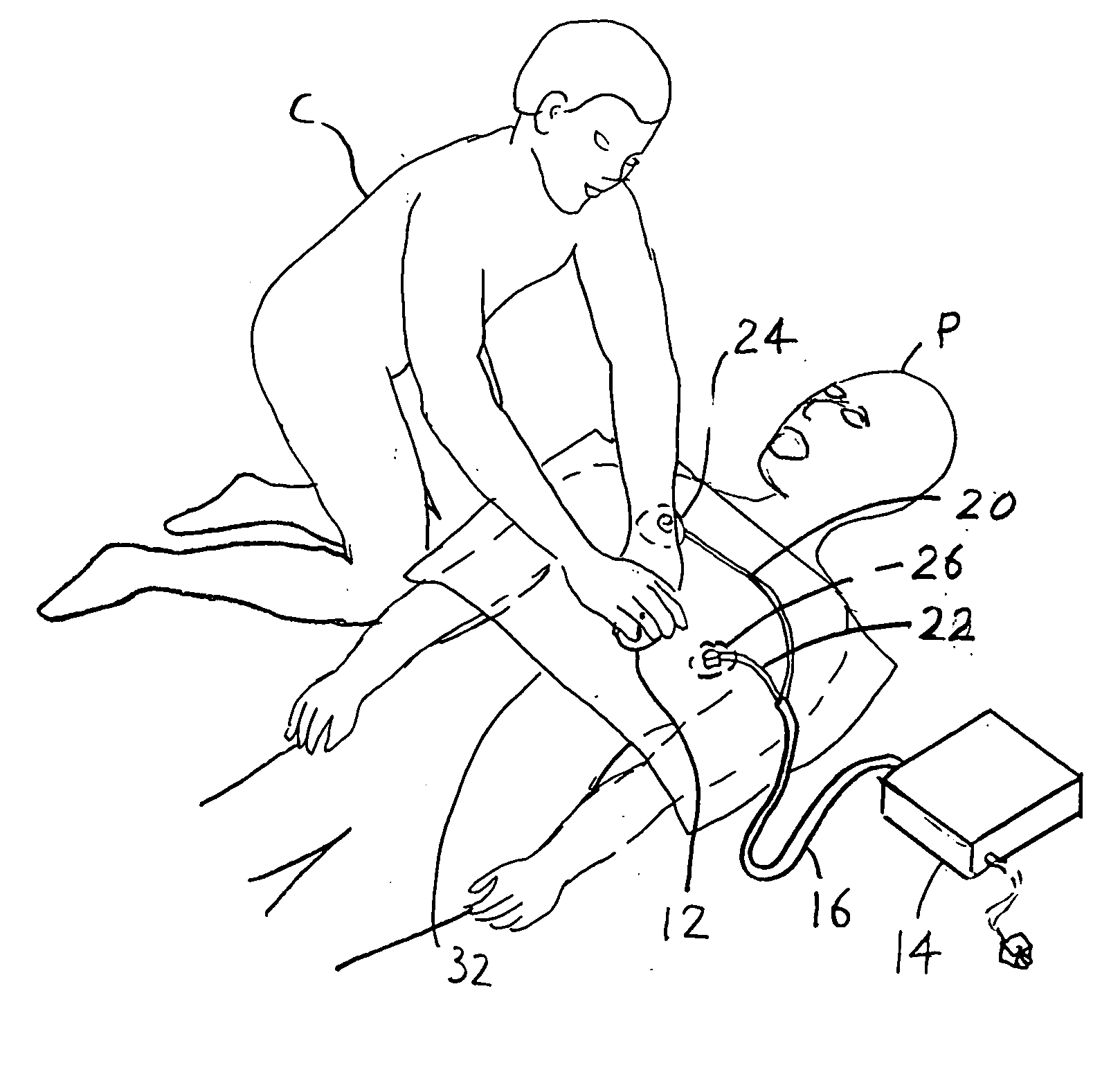
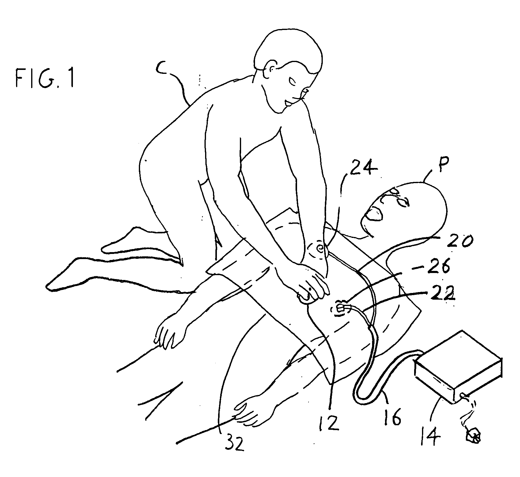
[0016]FIG. 1 illustrates a victim who has signs of cardiac arrest and who is being treated by a rescuer C. The rescuer may be a person who is a bystander and who has taken a CPR course. The rescuer has applied the electrodes of an AED (automatic external defibrillator) 14 that was available at the site of possible cardiac arrest, and is performing chest compressions at the lower chest area 12. The automatic defibrillator 14 can apply high-voltage (e.g. 2,800 volts) shocks when the intelligence built into the defibrillator confirms the presence of a rhythm that prompts delivery of an electrical shock. The defibrillator has a cable 16 with wires 20, 22 having conductors that are connected to first and second electrodes 24, 26. The electrodes are attached to the skin of the victim at conventional locations under the right collar bone and left lower chest. The rescuer applies downward forces or compressions to the sternum. It is noted that in some cases a rescuer also may blow air into ...


PUM


Abstract

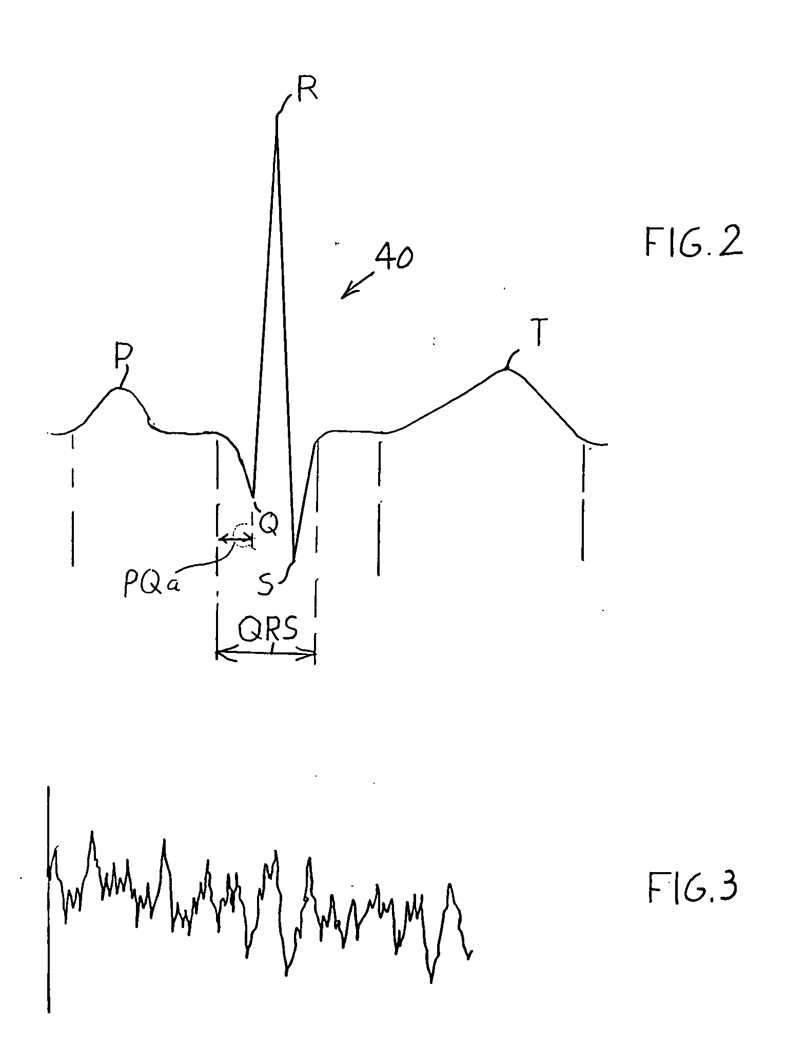
A method is provided for controlling an automatic external defibrillator without stopping CPR (primarily chest compressions). While chest compressions continue to be applied to the victim, the system differentiates between (1) a perfusing rhythm that has the capability of leading to a beating heart without a shock and (2) ventricular fibrillation (VF) which sometimes occurs in the presence of ventricular tachycardia (VT), in which there is no capability for leading to a beating heart without a shock. Defibrillation shocks should be applied only when needed and that is in the presence of VF and sometimes in the presence of VT. Electrocardiographic (ECG or EKG) signals obtained from electrodes applied to the patient's chest are analyzed so that the presence of a QRS signal characteristic of a rhythm which has the potential of supporting a beating heart, or the absence of a QRS signal which indicates ventricular fibrillation, may be detected in the presence of artifacts resulting from chest compressions.

Description

BACKGROUND OF THE INVENTION [0001] Automatic external defibrillators (AEDS) for treating cardiac arrests and especially in heart attack victims, are becoming more widely available. Before delivering shocks, current versions of AEDs analyze ECG (electrocardiographic) signals, which are sensed by electrodes attached to the victim's chest. The AED interprets the ECG (electrocardiographic) signals to determine whether a defibrillating shock to the patient's chest is indicated. Electrical shocks are harmful to the victim, although they are necessary for survival if the victim's heart is in a state of ventricular fibrillation (VF). Electrical shocks that are delivered to a heart that has a weak but detectable beat (which produces QRS signals) harm the patient by interfering with the capability to pump blood and by damaging the heart muscle. U.S. Pat. No. 6,393,316 describes a method for determining whether or not to apply a defibrillating shock. [0002] If other people are present at the o...

Claims


Application Information

Patent Timeline
IPC IPC(8): A61B5/361A61B5/363A61N1/39
CPCA61B5/046A61B5/0464A61B5/7239A61B5/726A61N1/3925A61B5/7207A61B5/361A61B5/363
Inventor YOUNG, CLAYTONBISERA, JOEWEIL, MAX HARRY
Owner ZOLL MEDICAL CORPORATION
Learn More