Coaxial cable connector

a technology of coaxial cable and connector, which is applied in the direction of connections, basic electric elements, electric devices, etc., can solve the problems of degrading the performance of the cable, reducing the use of radial crimp connectors, and reducing so as to reduce the insertion force of cables and facilitate the relative movement of connector components

Active Publication Date: 2011-03-29
IDEAL IND INC +1
View PDF17 Cites 43 Cited by
  • Summary
  • Abstract
  • Description
  • Claims
  • Application Information

AI Technical Summary

Benefits of technology

[0014]According to another aspect of the present disclosure, a coaxial cable connector is provided with a generally tubular mandrel. An attachment element and a retainer are associated with the mandrel, with a bushing being associated with the retainer. The bushing is adapted for movement along the retainer and the retainer is sufficiently translucent or transparent to permit visual observation of the cable jacket within the retainer. This allows the installer to know when the cable has been properly seated within the connector.
[0015]In another aspect of the present disclosure, some of the components of the connector may have a lubricant applied thereto to reduce the cable insertion force and make relative movement of the connector components easier.

Problems solved by technology

While such connectors are easily applied to a cable, many believe that they do not result in optimal signal transmission.
A perceived inability of such connectors to provide a water-tight seal between the connector and cable has led to a decreased use of radial crimp-type connectors.
An improperly fit connector-cable pair can become disengaged or provide an incomplete seal, which risks allowing moisture into the connector, thereby degrading the performance of the cable.
While O-rings are generally effective, they do add cost and complexity to the connector.
Press fitting parts of the connector together can also provide moisture seals but doing so adds to the complexity of the connector assembly process and the equipment needed in the factory.

Method used


Image

  • Coaxial cable connector
  • Coaxial cable connector
  • Coaxial cable connector

Examples


Embodiment Construction

[0027]The embodiments disclosed herein are for the purpose of providing the required description of the present subject matter. These embodiments are only exemplary, and may be embodied in various forms. Therefore, specific details disclosed herein are not to be interpreted as limiting the subject matter as defined in the accompanying claims.

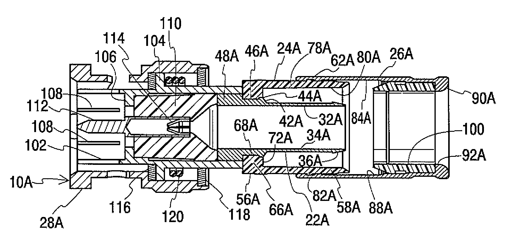
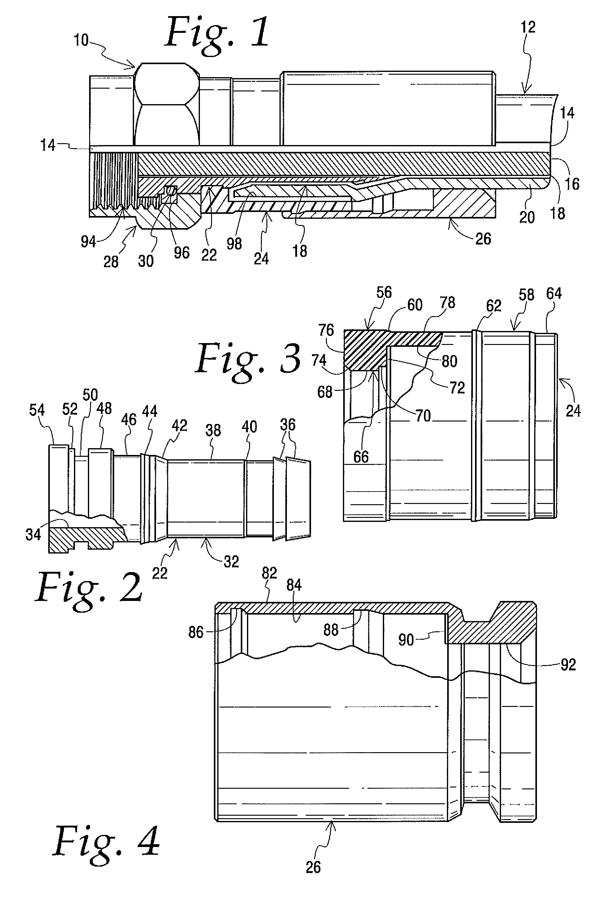
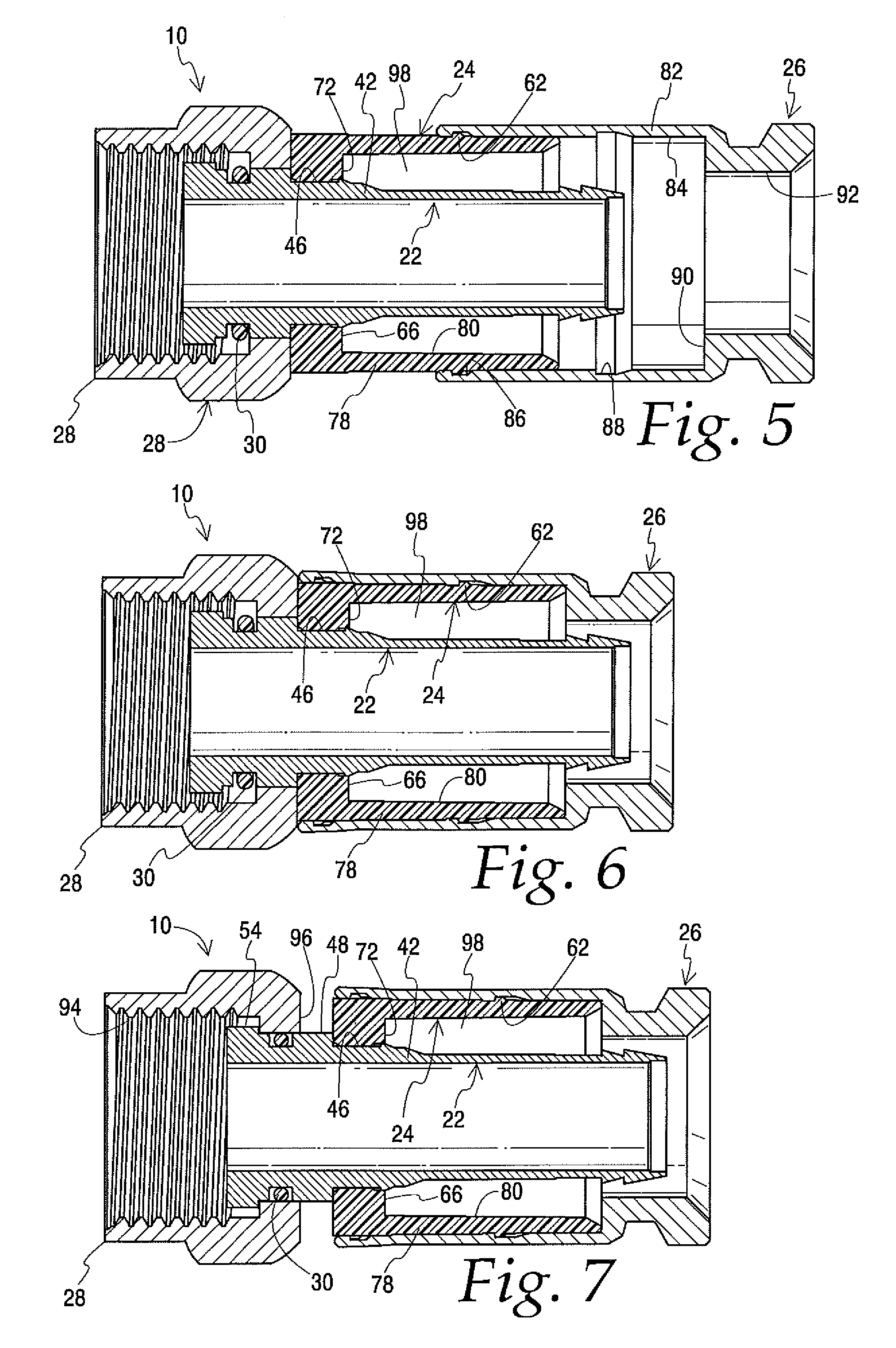
[0028]FIG. 1 shows a coaxial cable connector 10 suitable for use with a typical coaxial cable. The coaxial cable is shown generally at 12. Coaxial cable typically has a central conductor 14 at the center of the cable. The central conductor is usually made of copper or a copper-plated material. A cylindrical dielectric core 16 encloses the central conductor. A conductive shield 18 surrounds the dielectric core and an outer, insulative jacket 20 in turn surrounds the shield. The shield 18 is shown diagrammatically as a single layer. It will be understood that, depending on the application requirements, the shield may include a metallic foil layer ...


PUM


Abstract

A coaxial cable connector is provided with a generally tubular mandrel. An attachment element and a retainer are associated with the mandrel and a bushing is telescopically mounted on the retainer. The bushing is adapted for axial movement along the retainer to a closed position wherein the bushing biases a first portion of the retainer into sealing engagement with a seating surface on the exterior of the mandrel. The retainer is sufficiently translucent to permit visual observation of a cable inserted into the retainer.

Description

CROSS-REFERENCE TO RELATED APPLICATION[0001]This application claims the benefit of U.S. Provisional Application Ser. No. 61 / 104,797, filed Oct. 13, 2008, the disclosure of which is incorporated by reference herein.BACKGROUND OF THE INVENTION[0002]The present invention relates to connectors used to attach coaxial cable to a mating port. Coaxial cable is widely used for the transmission of data. A common application is the transmission of television signals from a provider or source to an end user. A typical RG-6 or RG-59 coaxial cable comprises a central conductor surrounded by a dielectric insulator or core, which in turn is surrounded by a conductive shield. The shield is surrounded by a flexible, outer insulative jacket. The conductive shield may include one or more layers of a metallic foil and / or a braided metallic sleeve.[0003]A free end of the coaxial cable is secured to a plug or port of a receiving unit by a coaxial cable connector. Releasable engagement elements are formed ...

Claims


Application Information

Patent Timeline
Patent Type & Authority Patents(United States)
IPC IPC(8): H01R9/05
CPCH01R9/0521Y10S439/91
Inventor SUTTER, ROBERT W.
Owner IDEAL IND INC
Why Eureka
Try Eureka