Sterile container

a sterile container and container body technology, applied in the field of sterile containers, can solve problems such as damage to sterile containers

Inactive Publication Date: 2011-03-29
AESCULAP AG
View PDF34 Cites 8 Cited by
  • Summary
  • Abstract
  • Description
  • Claims
  • Application Information

AI Technical Summary

Benefits of technology

[0011]A holding device is preferably provided for holding at least one part of the sterile barrier on the sterile container. This makes it possible to arrange the sterile barrier in a simple way on the sterile container, for example, to mount it thereon or connect it thereto.
[0039]It is advantageous when in the overpressure position the pressure prevailing in the environment outside of the sterile container exceeds the pressure prevailing in the receiving space by at least the minimum pressure difference. This means that the overpressure flow path is at least partially open when in the environment outside of the sterile container a pressure prevails, which is greater than the pressure prevailing in the receiving space by at least the minimum pressure difference. Accordingly, a pressure difference prevailing, for example, during sterilization of the sterile container can be reduced by at least partially opening the overpressure flow path and thereby allowing hot steam to flow into the receiving space. The variable flow cross section thus makes it possible for a kind of pressure relief valve to be created in the form of an inlet valve.

Problems solved by technology

During sterilization of the sterile container, large pressure differences between the environment outside of and the receiving space inside of the sterile container may arise and cause damage to the sterile container by, for example, the sterile container being compressed or inflated by pressure forces acting thereon.
To avoid damage, when a minimum pressure difference is exceeded, additional bypass flow paths are opened, which permit a high air mass exchange within a short time, which would not be possible via the sterile flow path.

Method used


Image

  • Sterile container
  • Sterile container
  • Sterile container

Examples


Embodiment Construction

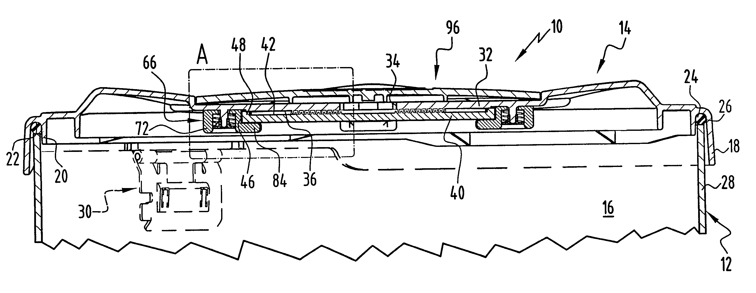
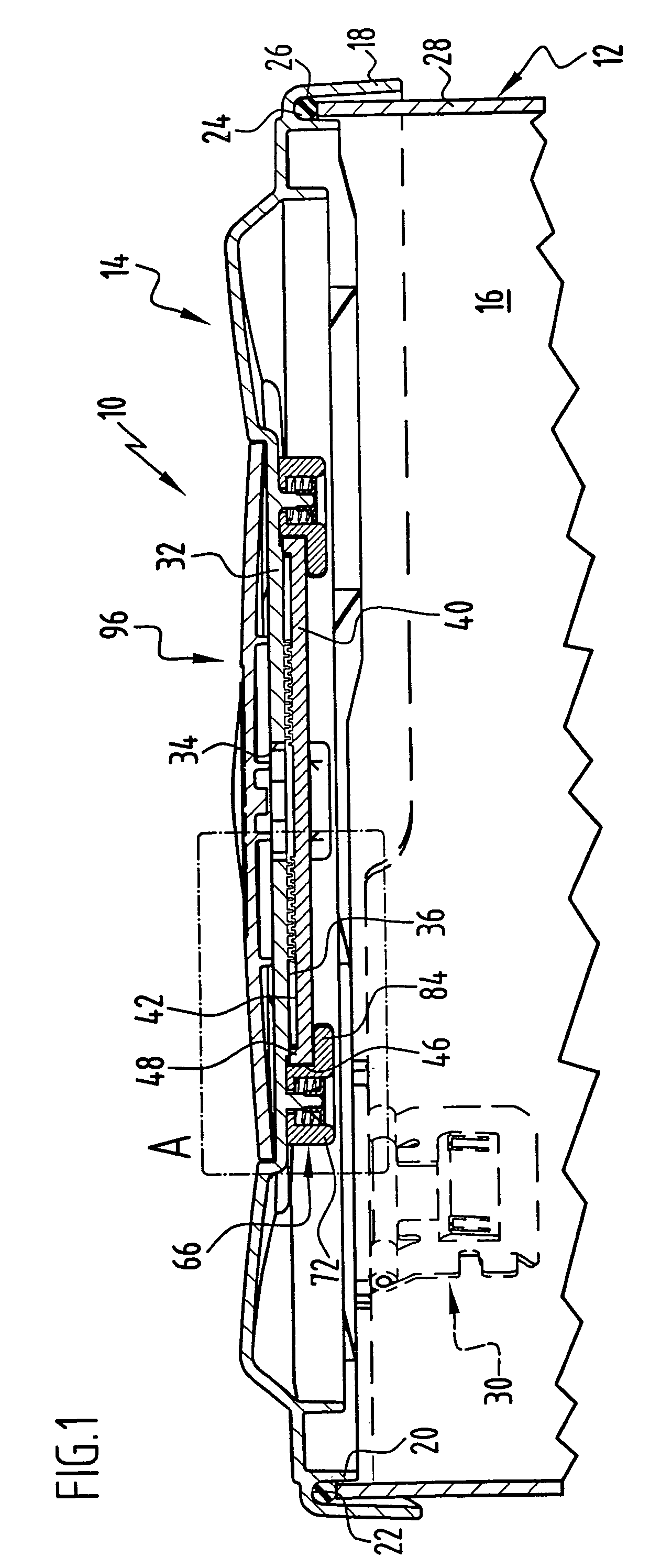
[0045]FIG. 1 shows a sterile container, generally designated by reference numeral 10, which comprises a container tray 12 and a lid 14 for closing the container tray 12. Surgical instruments and surgical material may, for example, be stored in an interior 16 of the sterile container 10.

[0046]The lid 14 has a vertically projecting, circumferential rim 18 and a somewhat shorter projection 20 extending parallel thereto. The rim 18 and the projection 20 define between them a circumferential sealing groove 22 in which a seal 24 is inserted. The sealing groove 22 serves to receive front edges 26 of walls 28 of the container tray 12. The seal 24 comes to rest directly on the front edges 26 and is compressed somewhat by two closure latches 30 arranged opposite one another on the lid 14, when locking the container tray 12, so that the lid 14 closes the container tray 12 in a gas-tight manner.

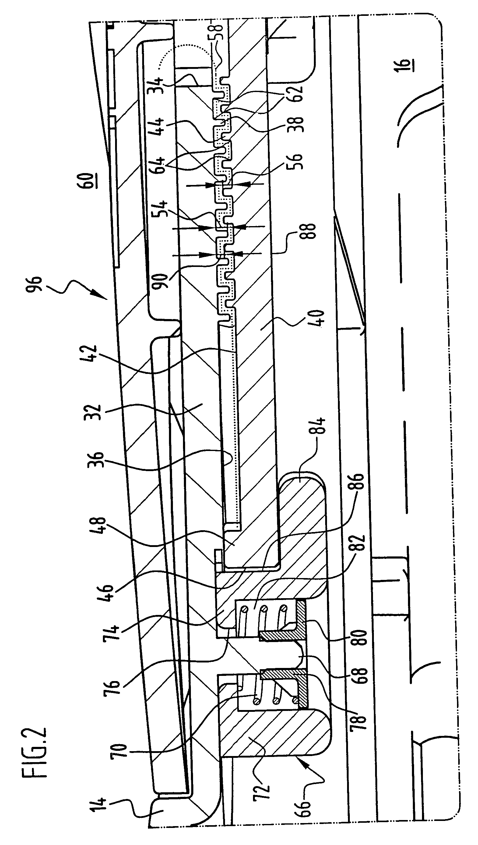
[0047]A circular inlet opening 34 is provided in a lid wall 32 at the center of the lid 14 and is sur...


PUM

PropertyMeasurementUnit
pressureaaaaaaaaaa
pressuresaaaaaaaaaa
thicknessaaaaaaaaaa

Abstract

To improve a sterile container, in particular, for receiving and storing surgical instruments or surgical material under sterile conditions, comprising a receiving space formed by a container bottom and container walls, a lid for closing the receiving space, a sterile barrier permanently defining a sterile flow path for establishing a fluid connection between the receiving space and an environment outside of the sterile container, and an overpressure flow path defining a fluid connection between the receiving space and the environment outside of the sterile container, wherein the overpressure flow path is closed when the sterile container is in a sterile position in which an exchange of gas between the receiving space and the environment outside of the sterile container is only possible through the sterile flow path, and wherein the overpressure flow path is at least partially open when the sterile container is in an overpressure position in which a pressure difference between pressures prevailing in the receiving space and in the environment outside of the sterile container exceeds a minimum pressure difference, so that design and maintenance of the sterile container are particularly simple, it is proposed that a gas flow cross section of the sterile flow path be alterable for formation of the overpressure flow path.

Description

[0001]This application is a continuation of international application number PCT / EP2005 / 003843 filed on Apr. 2, 2005.[0002]The present disclosure relates to the subject matter disclosed in international application number PCT / EP2005 / 003843 of Apr. 12, 2005 and German application number 10 2004 020 804.2 of Apr. 16, 2004, which are incorporated herein by reference in their entirety and for all purposes.BACKGROUND OF THE INVENTION[0003]The invention relates to a sterile container, in particular, for receiving and storing surgical instruments or surgical material under sterile conditions, comprising a receiving space formed by a container bottom and container walls, a lid for closing the receiving space, a sterile barrier permanently defining a sterile flow path for establishing a fluid connection between the receiving space and an environment outside of the sterile container, and an overpressure flow path defining a fluid connection between the receiving space and the environment outs...

Claims


Application Information

Patent Timeline
Patent Type & Authority Patents(United States)
IPC IPC(8): A61L2/00A61L9/00A61B19/02A61L2/26
CPCA61B19/026A61L2/26A61B2019/0213A61L2/07A61L2202/121A61L2202/182A61L2202/24A61B2050/006A61B50/30
Inventor OERTMANN, FRIEDRICH-WILHELM
Owner AESCULAP AG
Why Eureka
Try Eureka