Connector assembly having signal and ground terminals
a technology of connecting assembly and ground terminal, which is applied in the direction of coupling device connection, connection contact member material, coupling protective earth/shielding arrangement, etc., can solve the problems of reducing the overall size, increasing the cost of manufacturing the receptacle and the electronic device, and affecting the quality of transmitted signals in printed wiring boards, etc., to achieve the effect of suppressing the increase in the cost of manufacturing a printed wiring board and the quality drop of transmitted signals
- Summary
- Abstract
- Description
- Claims
- Application Information
AI Technical Summary
Benefits of technology
Problems solved by technology
Method used
Image

Examples
first embodiment
[0039](Configuration of Interface Between Electronic Devices)
[0040]The configuration of an interface between electronic devices according to the present embodiment will be described with reference to the drawings. Specifically, the present embodiment will describe an interface based on the HDMI (High-Definition Multimedia Interface)® standard as an example of an interface between electronic devices.
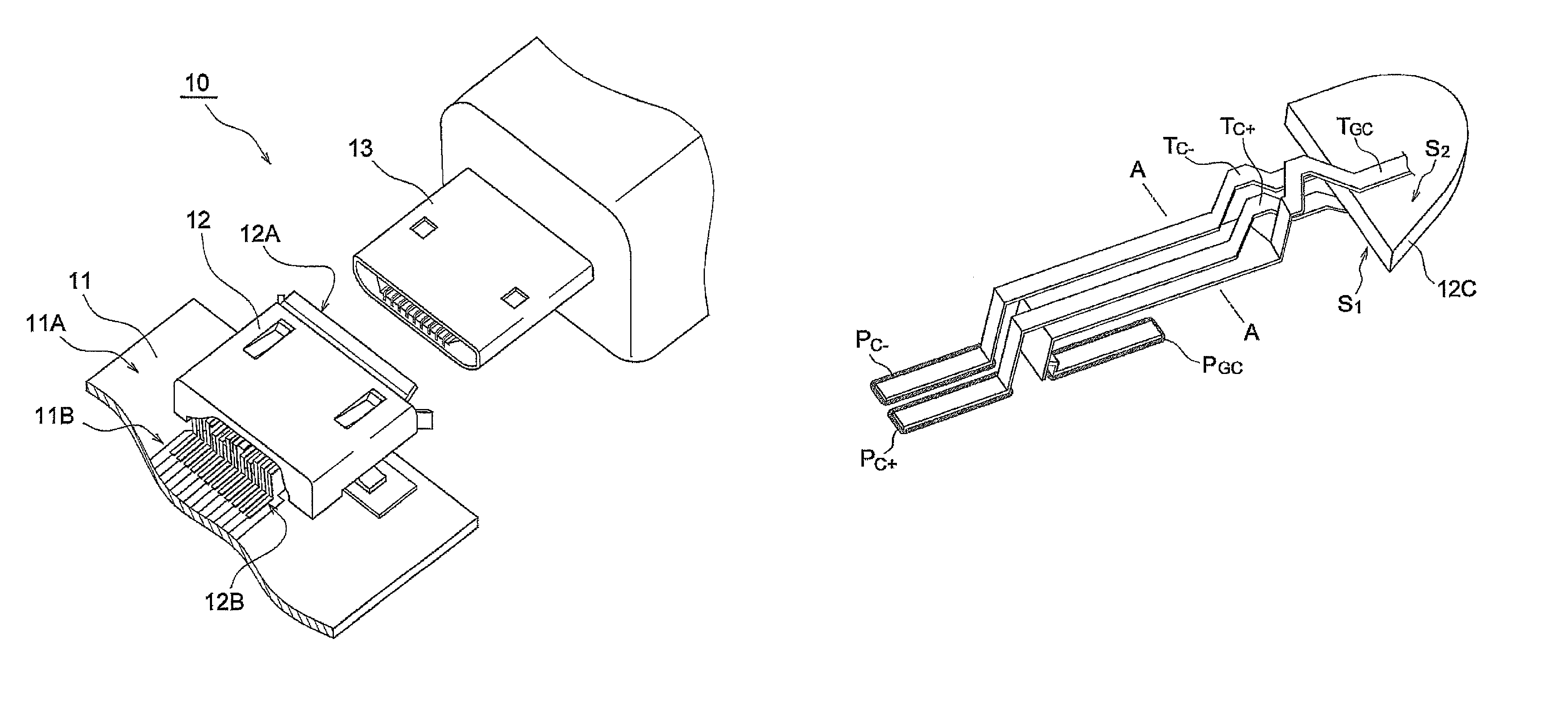
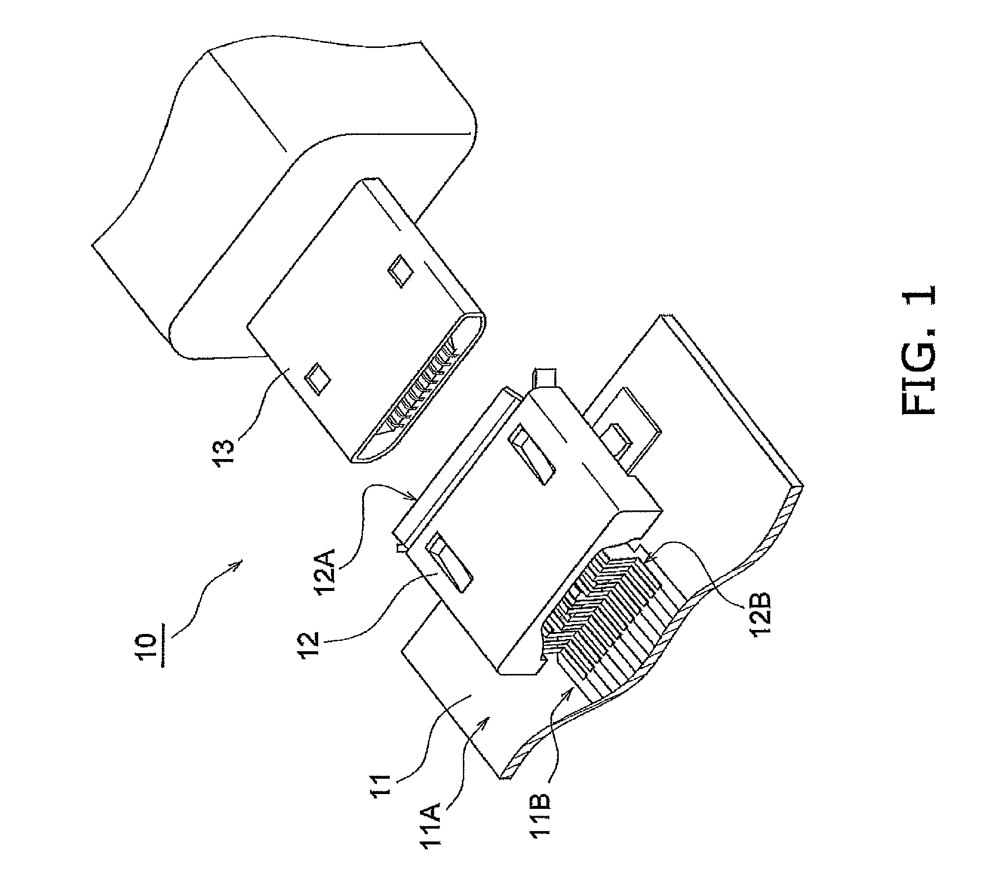
[0041]FIG. 1 is a perspective view illustrating the configuration of an interface 10 according to the present embodiment. As shown in FIG. 1, the interface 10 is configured of a printed wiring board 11, a receptacle 12, and a plug 13.
[0042]The printed wiring board 11 is installed within an electronic device (not shown) such as a personal computer. The printed wiring board 11 has a mounting surface 11A and a wire group 11B. The receptacle 12 and various components (not shown) are mounted upon the mounting surface 11A. The wire group 11B transmits signals between the receptacle 12 and the v...
second embodiment
[0107]Next, the configuration of a receptacle 12 according to a second embodiment will be described with reference to the drawings. Hereinafter, the differences from the first embodiment will mainly be described. The difference from the first embodiment is that the link portions of the bottom terminals TBTM are twisted by approximately 90 degrees.
[0108]Hereinafter, descriptions will be given using the configurations of the ground terminal TGC and the pair of signal terminals TC+ and TC− as examples. It should be noted that these configurations can also be applied to the ground terminal TG1 and the pair of signal terminals T1+ and T1−.
[0109](Configuration of Ground Terminal TGC and Pair of Signal Terminals TC+ and TC−)
[0110]The configuration of the ground terminal TGC and the pair of signal terminals TC+ and TC− will be described with reference to the drawings. FIG. 13 is a perspective view illustrating the ground terminal TGC and the pair of signal terminals TC+ and TC−. FIG. 14 is ...
third embodiment
[0119]Next, the configuration of a receptacle 12 according to a third embodiment will be described with reference to the drawings. Hereinafter, the differences from the first embodiment will mainly be described. The difference from the first embodiment is that the vertical positions of the ground terminal TGC and the pair of signal terminals TC+ and TC− are inverted within the terminal insulation plate 12C.
[0120]Hereinafter, descriptions will be given using the configurations of the ground terminal TGC and the pair of signal terminals TC+ and TC− as examples. It should be noted that these configurations can also be applied to the ground terminal TG1 and the pair of signal terminals T1+ and T1−.
[0121](Receptacle Configuration)
[0122]The configuration of the receptacle 12 according to the third embodiment will be described with reference to the drawings. FIG. 16 is a perspective view illustrating the receptacle 12 according to the third embodiment as viewed from the second primary surf...
PUM
 Abstract
Description
Claims
Application Information
 - R&D Engineer
- R&D Manager
- IP Professional
- Industry Leading Data Capabilities
- Powerful AI technology
- Patent DNA Extraction
Browse by: Latest US Patents, China's latest patents, Technical Efficacy Thesaurus, Application Domain, Technology Topic.
© 2024 PatSnap. All rights reserved.Legal|Privacy policy|Modern Slavery Act Transparency Statement|Sitemap