Coaxial mid-frequency and high-frequency loudspeaker

a loudspeaker and coaxial technology, applied in the field of coaxial loudspeakers, can solve the problems of inherently low q of the coaxial transducer, destroying the temporal coherence of the original signal, and implementing such coaxial transducers in loudspeakers

Active Publication Date: 2011-04-05
EAW NORTH AMERICA INC
View PDF7 Cites 7 Cited by
  • Summary
  • Abstract
  • Description
  • Claims
  • Application Information

AI Technical Summary

Problems solved by technology

The successful implementation of such coaxial transducers in loudspeakers, however, poses certain engineering challenges.
The conventional coaxial transducer 10 constructed in this manner, however, suffers from inherently low Q because it cannot be successfully loaded to a horn 20 for the following reason.
It would be intuitively obvious to one skilled in the art that this design would cause significant reflections off the walls of the horn 20, causing the acoustic signals to arrive at an observer (listener) at multiple times, thereby destroying the temporal coherence of the original signals and further creating various attendant problems (e.g., side lobes and transient smearing).

Method used


Image

  • Coaxial mid-frequency and high-frequency loudspeaker
  • Coaxial mid-frequency and high-frequency loudspeaker
  • Coaxial mid-frequency and high-frequency loudspeaker

Examples


Embodiment Construction

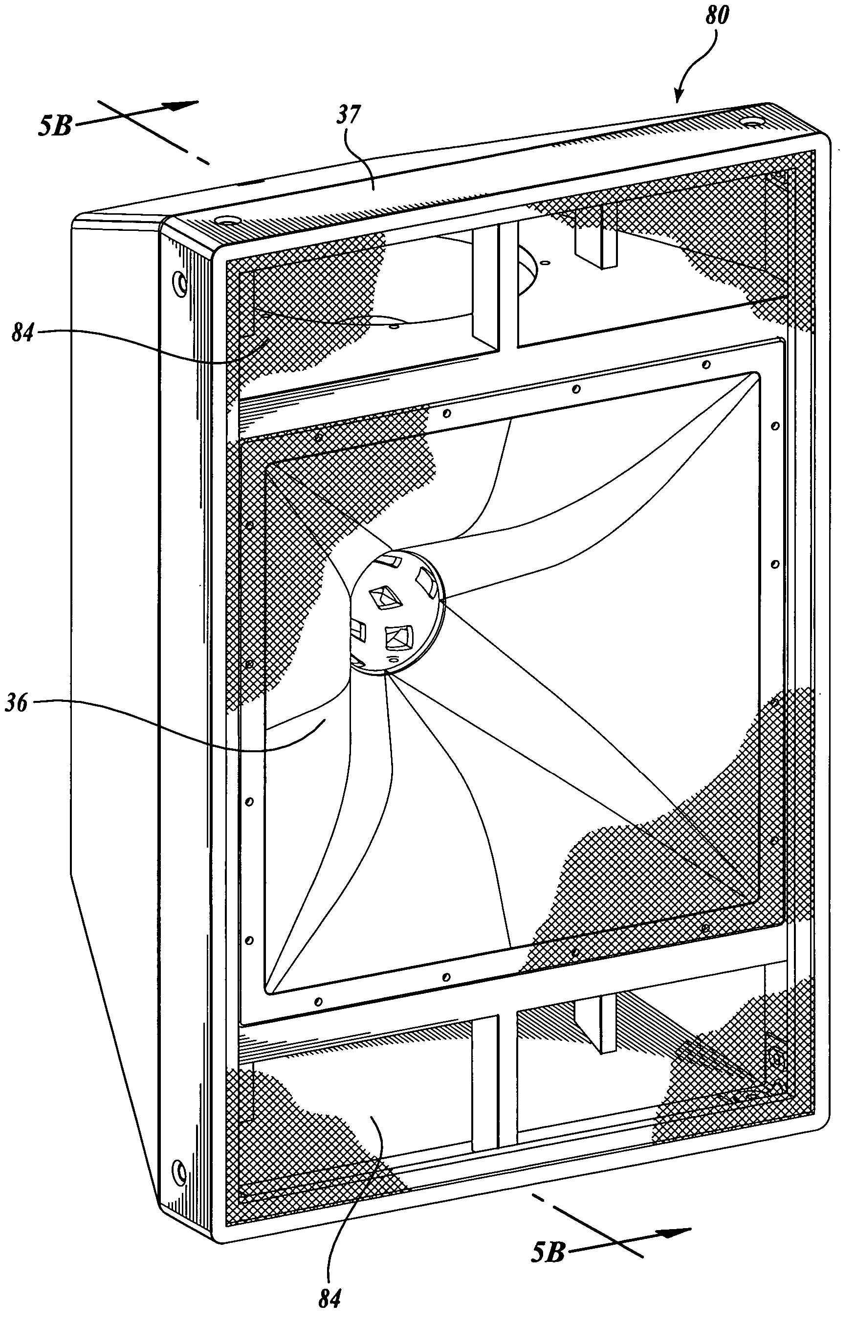
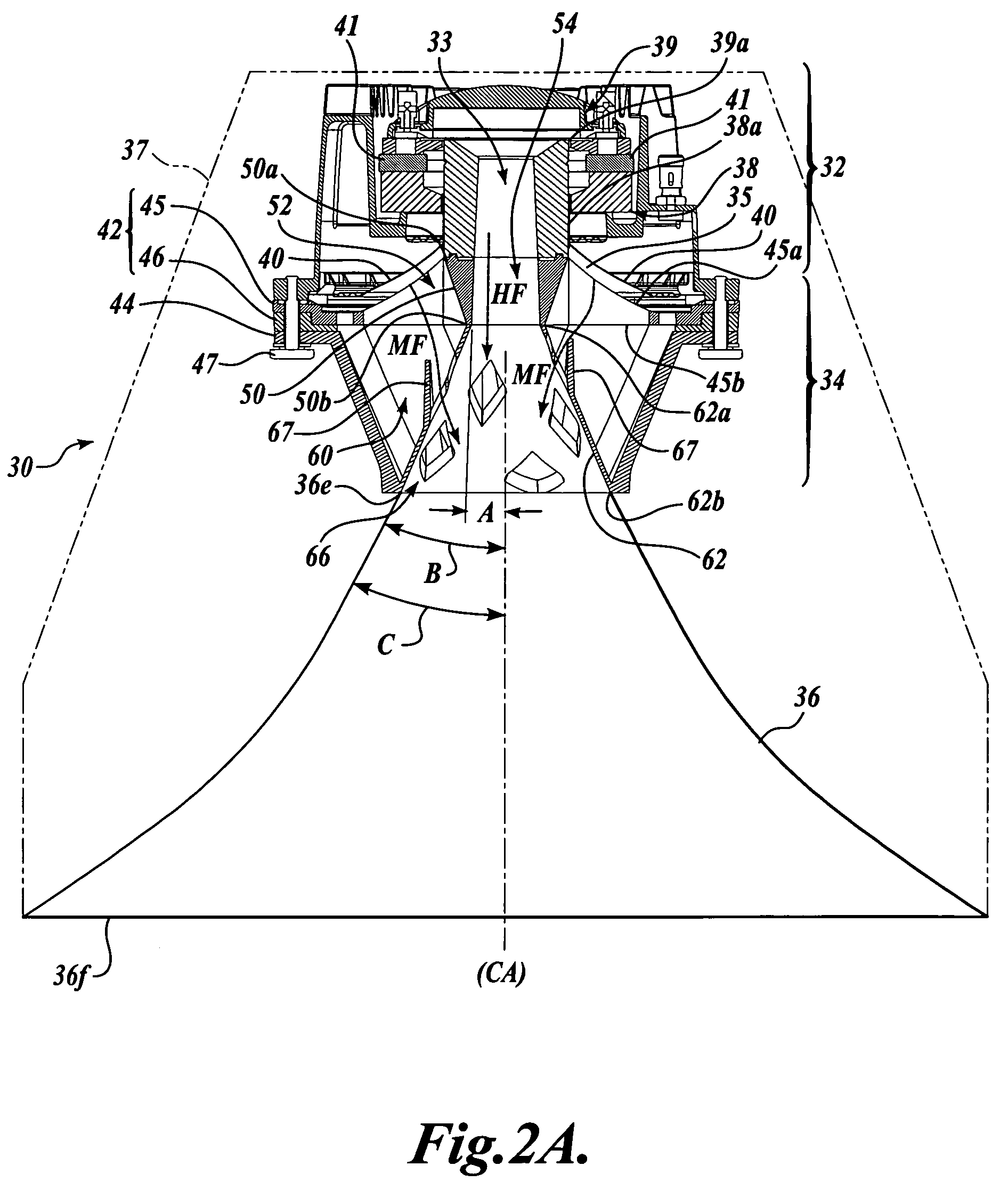
[0026]FIGS. 2A and 2B illustrate a coaxial mid-frequency (MF) and high-frequency (HF) loudspeaker 30 formed in accordance with one embodiment of the present invention. The loudspeaker 30 is configured to receive an electrical signal and transmit an acoustic signal through a transmission medium (e.g., through the air), and includes a coaxial transducer 32 and an acoustic transformer 34. The coaxial transducer 32 is a combination of two or more coaxially arranged drivers that each receives an electrical signal and produces an acoustic signal representative of the electrical signal, while the acoustic transformer 34 serves to match the coaxial transducer 32 to the transmission medium. As shown, the loudspeaker 30 may also include a horn 36 arranged adjacent to the acoustic transformer 34. As best shown in FIG. 2B, which is a front view of the loudspeaker 30, the horn 36 may have a rectangular mouth defined by four sidewalls 36a-36d. As will be apparent to one skilled in the art, the ho...


PUM


Abstract

A loudspeaker is provided for receiving an electrical signal and transmitting an acoustic signal through a transmission medium. The system includes generally two elements: a coaxial transducer and an acoustic transformer. The coaxial transducer includes a high-frequency driver and a mid-frequency driver that are coaxially arranged. The acoustic transformer is acoustically coupled to the coaxial transducer and includes an initial horn section that expands from a first end to a second end in a direction away from the coaxial transducer. The initial horn section defines a plurality of openings therethrough, such that the initial horn section is acoustically opaque to high-frequency acoustic signals to thereby function as a waveguide for the high-frequency acoustic signals, while it is acoustically transparent to mid-frequency acoustic signals.

Description

CROSS-REFERENCE TO RELATED APPLICATION[0001]The present application claims the benefit of U.S. Provisional Application No. 60 / 689,472, filed Jun. 10, 2005.FIELD OF THE INVENTION[0002]The present invention relates generally to loudspeakers and, more particularly, to loudspeakers that efficiently and accurately couple acoustic energy from both a mid-frequency electrical-acoustic transducer and a high-frequency electrical-acoustic transducer to the open air.BACKGROUND OF THE INVENTION[0003]A loudspeaker is a device which converts an electrical signal into an acoustic signal (i.e., sound) and directs the acoustic signal to one or more listeners. In general, a loudspeaker includes an electromagnetic transducer (also referred to as a “driver”) that receives and transforms the electrical signal into a mechanical vibration. The mechanical vibrations produce localized variations in pressure about the ambient atmospheric pressure, and the pressure variations propagate within the atmospheric m...

Claims


Application Information

Patent Timeline
Patent Type & Authority Patents(United States)
IPC IPC(8): H04R25/00
CPCH04R1/24
Inventor BUTLER, NATHAN DAVID
Owner EAW NORTH AMERICA INC
Why Eureka
Try Eureka