
Wing ice protection heater element network

a technology of heater elements and heater elements, applied in aircraft components, transportation and packaging, de-icing equipment, etc., can solve problems such as ineffectiveness, ice may continue to build up, and ice icing on the wing

Inactive Publication Date: 2011-04-12
HONEYWELL INT INC
View PDF15 Cites 9 Cited by
  • Summary
  • Abstract
  • Description
  • Claims
  • Application Information

AI Technical Summary

Problems solved by technology

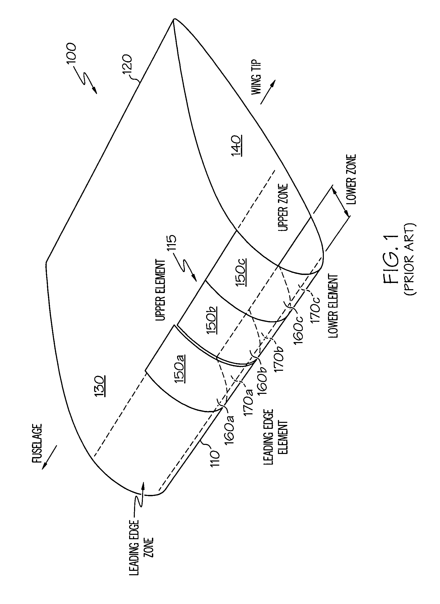
One of the problems encountered in modern day aviation is that of wing icing, where ice forms over the leading edges of the wings and control surfaces of an aircraft.
Either method will cause the deicer boot to expand beyond the standard airfoil profile and thus mechanically break the ice away from the leading edge of the airfoil.
In such conditions, ice may continue to build up while the deicer boot is rendered ineffective, since it only expands within the ice cavity and therefore has no effect on the built up ice.
The heat from this bleed air is sufficient to warm the wing to the point that it melts the ice interface, which causes the ice build-up to slide off the wing.
However, a major disadvantage of this approach is that it reduces the efficiency of the engine, uses more fuel, and requires more complex designs to provide effective ducting.
Error or failure conditions present special problems for WIP networks.
During standard operation, an individual heater element may fail through damage from foreign objects impacting the wing, material fatigue, or other causes.
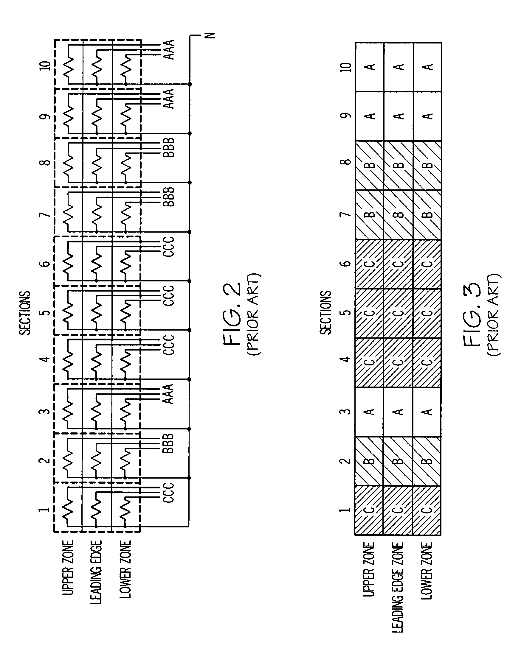
Referring to FIGS. 2 and 3, the WIP heating network shown will experience a phase imbalance when all three heater elements in the section containing the failed heater element must be deactivated, since each section is powered by a single phase, which would have a high probability of exceeding the maximum allowable threshold for phase imbalance.
However, the WIP Heating Network of FIGS. 4 and 5 shows that all power to the upper zone is supplied by Phase A, all power to the leading edge zone is supplied by Phase B, and all power to the lower zone is supplied by Phase C. If only a single zone were activated, e.g. the lower zone powered by Phase C, then a severe load imbalance would result, which would in all probability exceed the maximum threshold value.

Method used


Image

  • Wing ice protection heater element network
  • Wing ice protection heater element network
  • Wing ice protection heater element network

Examples


Embodiment Construction

zones of the same type, according to the prior art;

[0023]FIG. 5 is a logical map of the heating areas of an airfoil powered according to the second schematic diagram, in which one phase of three phase power supplies all power to all zones of the same type, according to the prior art;

[0024]FIG. 6 is a schematic diagram of the WIP heating network powering arrangement, according to an embodiment of the present invention;

[0025]FIG. 7 is a logical map of the heating areas of an airfoil configured according to an embodiment of the invention; and

[0026]FIG. 8 is a flowchart depicting a method of arranging sections and zones along a surface of an airfoil that ensures that electrical load is balanced across all power phases, according to an embodiment of the invention.

DETAILED DESCRIPTION OF THE INVENTION

[0027]The following detailed description is of the best currently contemplated modes of carrying out the invention. The description is not to be taken in a limiting sense, but is made merely ...


PUM


Abstract

An ice prevention network comprising a plurality of non-overlapping heater elements arranged in a grid along an airfoil is provided, powered by a multiphase power source, each phase powering selected heater elements that can selectively be powered on and powered off. The grid has a number of zones extending along the airfoil perpendicular to the airflow over the airfoil and a number of sections extending along the surface of the airfoil parallel to the airflow over the airfoil. Each of the heater elements is assigned to a single power phase and arranged such that an arbitrary section may be deactivated without causing a phase imbalance of more than one heating unit and such that a single zone may be activated without causing a phase imbalance of more than one heating unit.

Description

CROSS-REFERENCES TO RELATED APPLICATION[0001]This application claims the benefit of U.S. Provisional Patent Application Ser. No. 60 / 866,022, filed on Nov. 15, 2006, the contents of which are hereby incorporated by reference in their entirety.BACKGROUND OF THE INVENTION[0002]The present invention relates to ice protection networks of heater elements used in anti-ice and de-ice systems for prevention and removal of ice from aircraft airfoils, and more particularly, for the balancing of electrical loads between the heater elements comprising the overall deicing system to accommodate malfunctions and selective heater element activation.[0003]One of the problems encountered in modern day aviation is that of wing icing, where ice forms over the leading edges of the wings and control surfaces of an aircraft. Several methods have been devised to deal with this problem. One way is through the use of deicer boots installed along the leading edge of the airfoil. Deicer boots are typically cons...

Claims


Application Information

Patent Timeline
Patent Type & Authority Patents(United States)
IPC IPC(8): B64D15/14
CPCB64D15/14
Inventor KUMAR, MUKESHYUE, EDWIN WING-KWONGLAZAROVICH, DAVID
Owner HONEYWELL INT INC
Learn More