Inphase/quadrature phase imbalance compensation

a transceiver and imbalance compensation technology, applied in the field ofquadrature modulation, can solve the problems of insufficient compensation of inphase/quadrature phase imbalances, inability to simply eliminate i/q imbalances from analog components of ic transceivers, and incorporation of significant extra circuitry to collect feedback, so as to reduce i/q imbalances and reduce roundtrip. , the effect of reducing the imbalan

Inactive Publication Date: 2006-05-25
LUCENT TECH INC
View PDF5 Cites 28 Cited by
  • Summary
  • Abstract
  • Description
  • Claims
  • Application Information

AI Technical Summary

Benefits of technology

[0010] Another embodiment features a method of reducing inphase/quadrature phase (I/Q) imbalances in a transceiver. The method includes updating a configuration of one or more I/Q compensators

Problems solved by technology

In these architectures, the transceivers often produce imbalances between the parallel signal streams that are associated with inphase (I) and quadrature phase (Q) components of modulated carriers.
Often, such I/Q imbalances result from errors related to the limited tolerance in the micro-fabrication of integrated circuits (

Method used


Image

  • Inphase/quadrature phase imbalance compensation
  • Inphase/quadrature phase imbalance compensation
  • Inphase/quadrature phase imbalance compensation

Examples


example 1

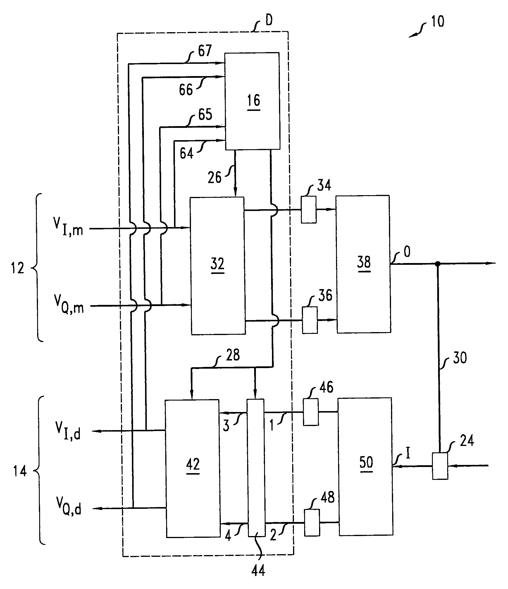
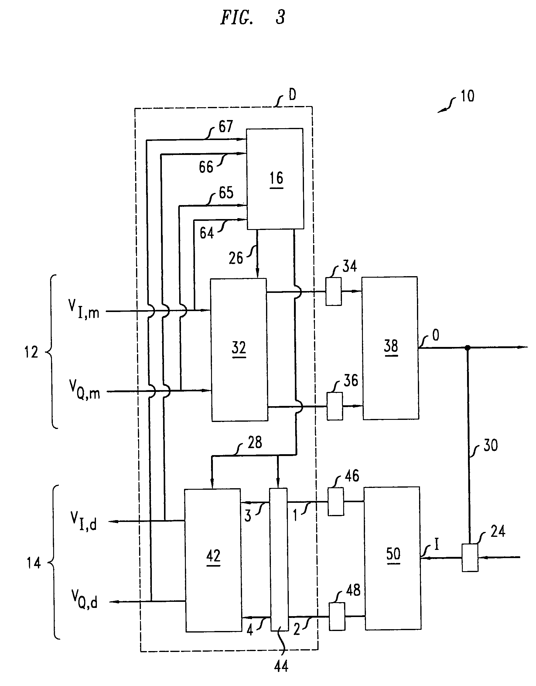
[0052]FIGS. 9A-9E illustrate the method 70 for an exemplary embodiment of transceiver 10. In the exemplary embodiment, the A circuit of the transmitter 12 has an I / Q imbalance that is a pure gain, gT, wherein gT=2. Similarly, in the exemplary embodiment, the A circuit of the receiver 14 has an I / Q imbalance that is a pure gain, gR, wherein gR=8. The method 70 evolves the gains gmc and gdc of the I / Q digital compensators 32, 42.

[0053] At step 72, the method 70 involves initializing the gain of both the I / Q pre-compensator 32 and the I / Q post-compensator 42 to one, i.e., gmc(0)=gdc(0)=1 as in FIG. 9A. Thus, the roundtrip I / P gain imbalance, g, i.e., g=|VI,m(k) / VQ,d(k)| / |VI,d(k) / VQ,d(k)|, initially satisfies: g=1×2×8×1=16.

[0054] At step 74, the method 70 involves iteratively rescaling the values of the gains of I / Q compensators 32, 42 while switch 44 is in mode A. The above-described iterative update formulas imply that each of the iterations will multiply the gain of both I / Q compen...

example 2

[0059]FIG. 10 shows a simulation of the evolution of the compensating I / Q gains and I / Q phases in another transceiver when these imbalances were corrected by the method 70 of FIG. 7. In the simulation, the A circuit of transmitter 12 has an initial I / P gain of 1.02 and an initial I / P phase of 2 degrees, and the A circuit of the receiver 14 has an initial I / P gain of 1.04 and an initial I / P phase of 4 degrees. The simulated results of FIG. 10 show that about 22 iterations in mode A and about 20 iterations in mode B suffice to compensate the I / P imbalances of both the transmitter 12 and receiver 14 for this exemplary embodiment. Thus, small I / Q imbalances can be rapidly dynamically compensated.


PUM


Abstract

A transceiver includes a transmitter, a receiver, and an electrical feedback line. The transmitter has a quadrature-modulator and is configurable to compensate inphase/quadrature phase imbalances produced by hardware of the transmitter. The quadrature-modulator is configured to quadrature-modulate a carrier wave. The receiver has a quadrature-demodulator and is configurable to compensate for inphase/quadrature phase imbalances produced by hardware in the receiver. The quadrature-demodulator is configured to demodulate a quadrature-demodulated carrier. The electrical feedback line connects an output of the transmitter to an input of the receiver.

Description

BACKGROUND [0001] 1. Field of the Invention [0002] The invention relates generally to quadrature-modulation and relates more particularly to methods and apparatus for compensating inphase / quadrature phase imbalance in transceivers. [0003] 2. Discussion of the Related Art [0004] Some radio frequency (RF) transceivers provide direct or low intermediate frequency (IF) conversion architectures in which single-stage quadrature-modulation is available without bulky analog filters. In these architectures, the transceivers often produce imbalances between the parallel signal streams that are associated with inphase (I) and quadrature phase (Q) components of modulated carriers. These I / Q imbalances can include amplitude and / or phase mismatches of about one to three percent. Often, such I / Q imbalances result from errors related to the limited tolerance in the micro-fabrication of integrated circuits (ICs). Thus, I / Q imbalances cannot simply be eliminated from analog components of IC transceiv...

Claims


Application Information

Patent Timeline
IPC IPC(8): H04L5/16
CPCH04B1/30H04L27/364H04L27/3863H04L2027/0016H04L2027/0022
Inventor CHEN, HSIN-HUNGCHEN, JIUNN-TSAIRCHEN, YOUNG-KAIHUANG, PO-CHIUNTU, KUN-YII
Owner LUCENT TECH INC
Why Eureka
Try Eureka