Wireless quadrature modulator transmitter using E/O and O/E connectives

a quadrature modulator and transmitter technology, applied in the field of wireless quadrature modulator transmitters using o/e connectives, can solve the problems of difficult to ensure linearity, small distortion, and difficulty in sufficiently increasing the output level of quadrature modulators, and achieves low power consumption, good linearity, and high transmission output power efficiency.

Inactive Publication Date: 2006-01-24
PANASONIC CORP
View PDF13 Cites 24 Cited by
  • Summary
  • Abstract
  • Description
  • Claims
  • Application Information

AI Technical Summary

Benefits of technology

[0010]Considering such problems in the prior art transmitting circuit apparatuses, an object of the present invention is to provide a transmitting circuit apparatus having a good linearity, a high transmission output power efficiency, and a small power consumption.
[0014]Yet another aspect of the present invention is a transmitting circuit apparatus, further comprising a first and a second band-pass filter for reducing unnecessary signals outside the transmission frequency band from said signals generated by modulating said carrier waves each having a phase perpendicular to each other by using said modulated I and Q signals, respectively, wherein said signals go through said first and second band-pass filters, respectively, and are then synthesized into an output signal of said quadrature modulator.
[0015]Still yet another aspect of the present invention is a transmitting circuit apparatus, further comprising a band-pass filter connected to the output of said quadrature modulator and for outputting a signal after reducing unnecessary signals outside the transmission frequency band from the output signal of said quadrature modulator.

Problems solved by technology

Accordingly, it is difficult to sufficiently increase the output level of the quadrature modulator 403.
Thus, the power amplifier 411 is used for amplification, however, the power amplifier 411 also needs to be operated in the linear range causing only smaller distortion.
Accordingly, in spite of the simple configuration of the slave station, the linearity is difficult to ensure, and there is a problem of large power consumption.

Method used


Image

  • Wireless quadrature modulator transmitter using E/O and O/E connectives
  • Wireless quadrature modulator transmitter using E/O and O/E connectives
  • Wireless quadrature modulator transmitter using E/O and O/E connectives

Examples


embodiment 1

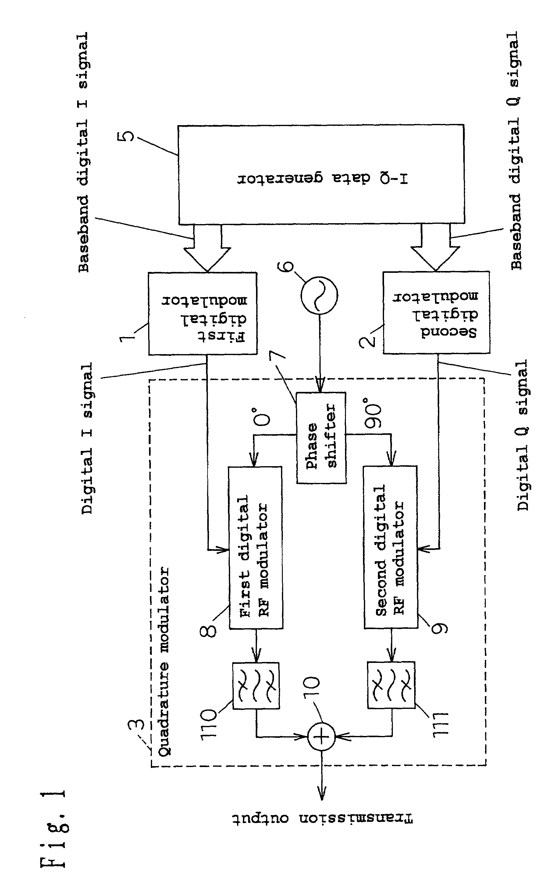
[0077]FIG. 1 is a configuration diagram of a transmitting circuit apparatus in accordance with Embodiment 1 of the present invention. In FIG. 1, numeral 1 indicates a first digital modulator. Numeral 2 indicates a second digital modulator. Numeral 3 indicates a quadrature modulator. Numeral 5 indicates an I-Q data generator. Numeral 6 indicates a local oscillator. The quadrature modulator 3 is composed of a phase shifter 7, a first digital RF modulator 8, a second digital RF modulator 9, a first band-pass filter 110, a second band-pass filter 111, and a synthesizer 10.

[0078]The operation of the above-mentioned transmitting circuit apparatus of Embodiment 1 is described below with reference to the drawings.

[0079]First, the I-Q data generator 5 outputs a baseband I signal to the first digital modulator 1, and outputs a baseband Q signal to the second digital modulator 2. Here, the baseband I and Q signals are multi-valued digital signals. The first digital modulator 1 performs sigma-d...

embodiment 2

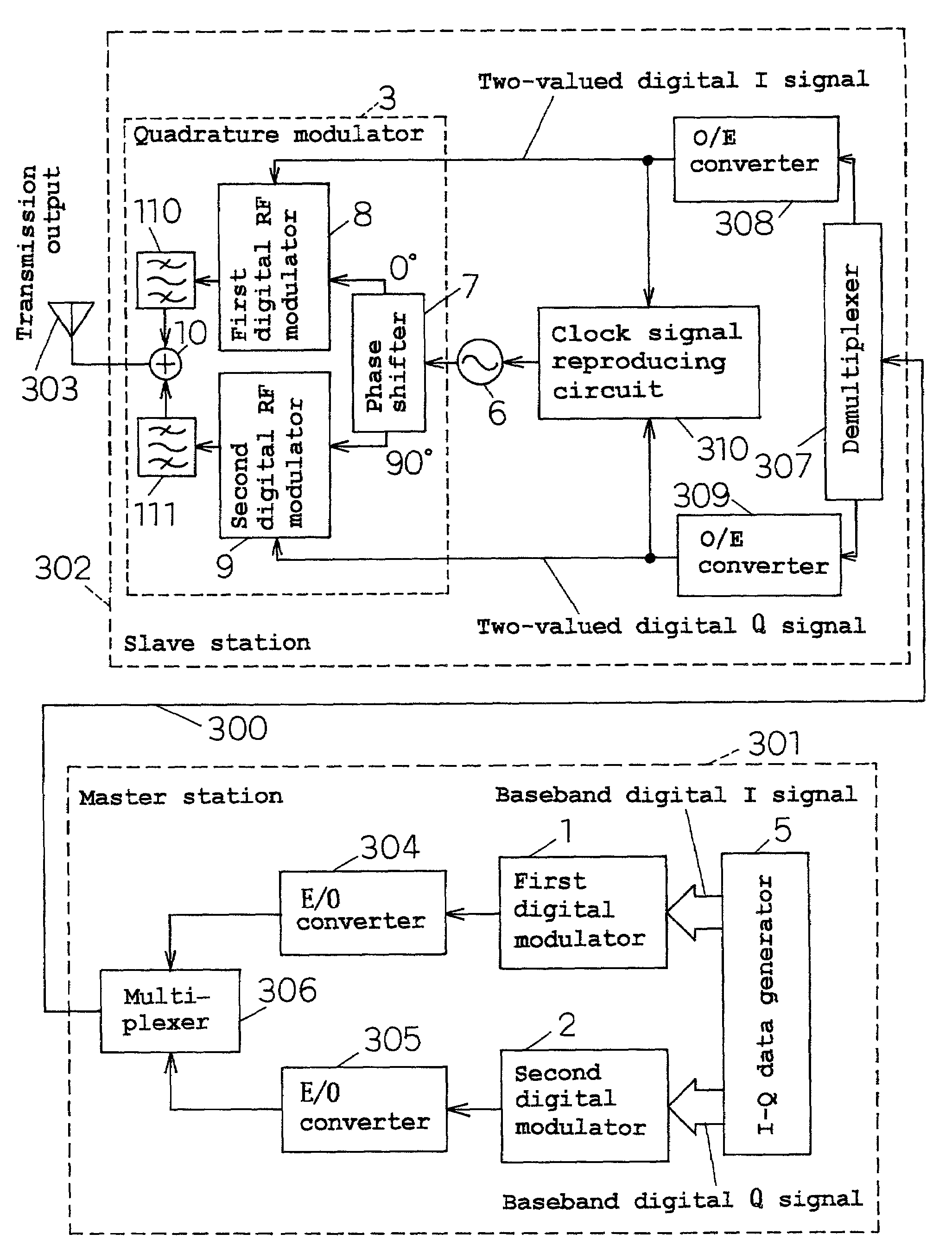
[0112]FIG. 9 shows the configuration of a transmitting circuit apparatus in accordance with Embodiment 2 of the present invention. In FIG. 9, a digital modulator and a quadrature modulator are interconnected with an optical fiber in the configuration of the transmitting circuit apparatus of Figure 1. Like numerals are assigned to the like parts to FIG. 1, and the detailed description is omitted. Further, like description to FIGS. 2 to 8 are also omitted.

[0113]In FIG. 9, numeral 300 indicates an optical fiber. Numeral 301 indicates a master station. Numeral 302 indicates a slave station. Numeral 303 indicates an antenna. Numerals 304 and 305 indicate E / O converters. Numeral 306 indicates an multiplexer. Numeral 307 indicates an demultiplexer. Numerals 308 and 309 indicate O / E converters. Numeral 310 indicates a clock signal reproducing circuit. The output signals of the digital modulators 1, 2 are converted into optical signals by the E / O converters 304, 305, respectively. Each E / O c...


PUM


Abstract

A transmitting circuit apparatus has a first digital modulator and a second digital modulator for modulating an I signal and a Q signal which are multi-valued digital baseband modulation signals, into a digital I signal and a digital Q signal, respectively, having the number of bits smaller than that of the baseband modulation signals; and a quadrature modulator for outputting a signal synthesized from the signals generated by modulating (two) carrier waves each having a phase perpendicular to each other by using the modulated I and Q signals, respectively.

Description

BACKGROUND OF THE INVENTION[0001]1. Field of the Invention[0002]The present invention relates to a transmitting circuit apparatus comprising a quadrature modulator used in wireless communications and the like.[0003]2. Related Art of the Invention[0004]In a transmitting circuit apparatus used in digital wireless communications by a modulation scheme such as QPSK, a quadrature modulator i s generally used as a modulator. FIG. 15 shows the basic configuration of a prior art transmitting circuit apparatus. In FIG. 15, numeral 403 indicates a quadrature modulator. Numeral 404 indicates a band-pass filter. Numeral 405 indicates an I-Q signal generator. Numeral 406 indicates a local oscillator. Numeral 407 indicates a phase shifter. Numerals 408 and 409 indicate mixers. Numeral 410 indicates a synthesizer. Numeral 411 indicates a power amplifier. The quadrature modulator 403 is composed of the phase shifter 407, the mixer 408, the mixer 409, and the synthesizer 410. The I-Q signal generato...

Claims


Application Information

Patent Timeline
Patent Type & Authority Patents(United States)
IPC IPC(8): H04L27/36H04L5/12H04L23/02H03F3/24
CPCH03F3/24H04L27/362H03F2200/331
Inventor ADACHI, HISASHIIIDA, MASANORIASAKURA, HIROYUKI
Owner PANASONIC CORP
Why Eureka
Try Eureka