Transmitting circuit apparatus and method

a transmission circuit and circuit technology, applied in the field of transmission circuit apparatus and method used in radio communication, can solve the problems of inability to make the power consumption of the whole transmitting circuit apparatus small, difficult to achieve linearity, and difficulty in enlarge the output level of the orthogonal modulator sufficiently, etc., to achieve good linearity, small power consumption, and high transmission output power efficiency

Active Publication Date: 2006-03-14
PANASONIC CORP
View PDF2 Cites 91 Cited by
  • Summary
  • Abstract
  • Description
  • Claims
  • Application Information

AI Technical Summary

Benefits of technology

[0019]In consideration of the above-described issues, the present invention aims to provide a transmitting circuit apparatus and method having good linearity, high transmission output power efficiency, and small power consumption.
[0027]Yet still another aspect of the present invention is the transmitting circuit apparatus, comprising a band pass filter which reduces an unnecessary signal out of a transmitted frequency band of an output signal of the amplitude modulator and outputs the output signal.
[0036]wherein the loop filter reduces an unnecessary signal from the phase-compared signal, and

Problems solved by technology

Therefore, it is difficult to sufficiently enlarge an output level of the orthogonal modulator 403.
Therefore, since the power consumption of the power amplifier 411 is large, it is not possible to make the power consumption of the whole transmitting circuit apparatus small.
Therefore, although the configuration of the slave station is simple, it becomes difficult to obtain linearity as power consumption increases substantially.
Thus, a conventional transmitting circuit apparatus has an issue that power consumption cannot be made small.

Method used


Image

  • Transmitting circuit apparatus and method
  • Transmitting circuit apparatus and method
  • Transmitting circuit apparatus and method

Examples


embodiment 1

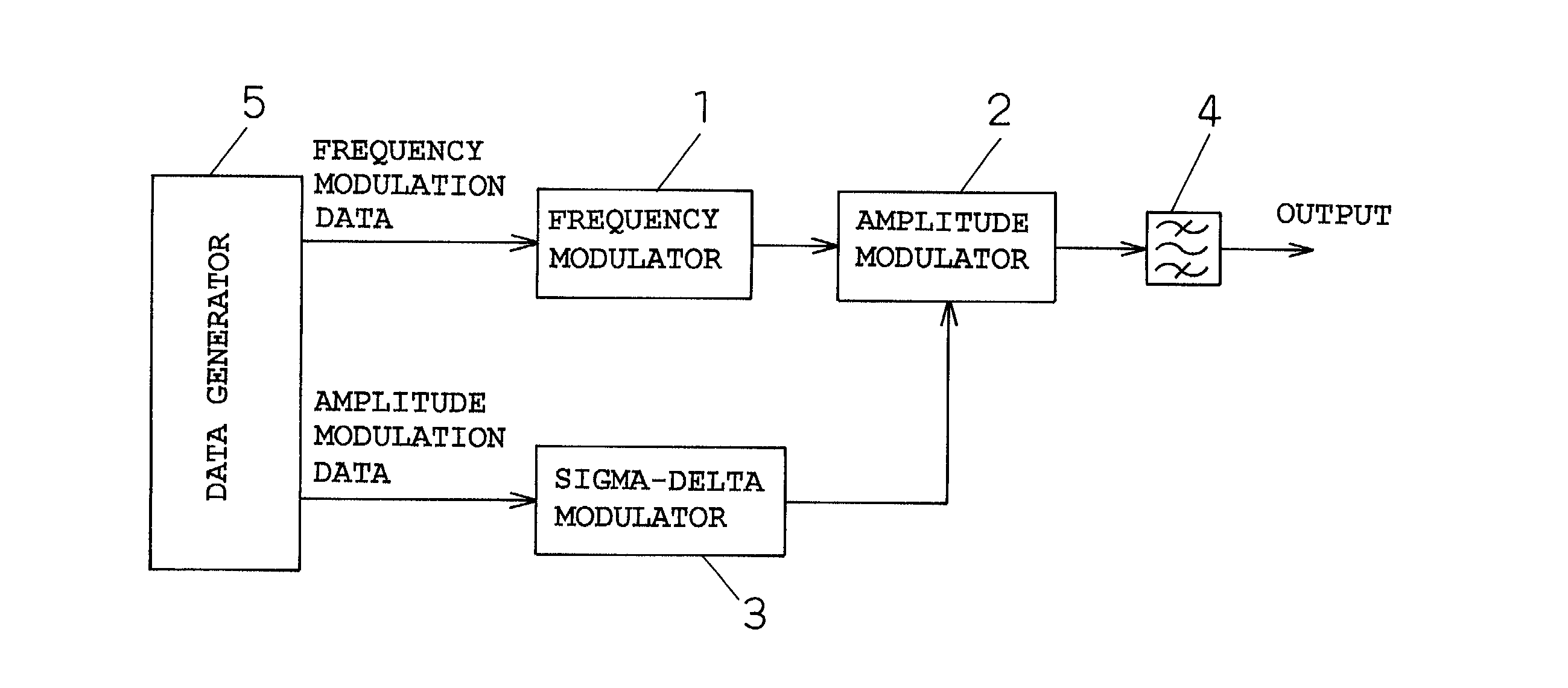
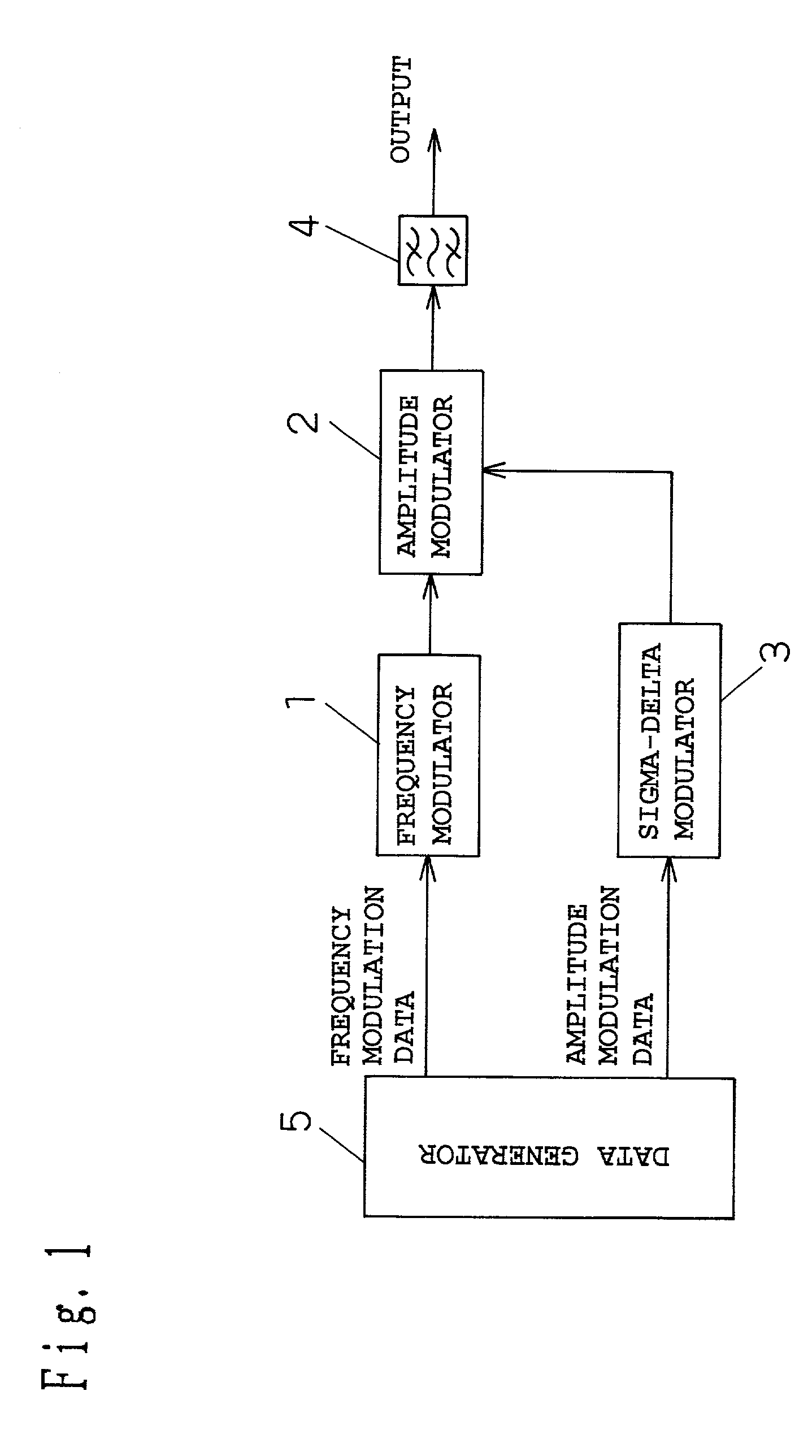
[0082]A basic configuration of a transmitting circuit apparatus according to an embodiment of the present invention is shown in FIG. 1. That is, FIG. 1 shows a frequency modulator 1, an amplitude modulator 2, a sigma-delta modulator 3, a band pass filter 4, and a data generator 5.

[0083]The data generator 5 is means of outputting vector modulation data constituted by frequency modulation data that is a digital signal, i.e., that has discrete values, and amplitude modulation data that is a digital signal, i.e., that has discrete values.

[0084]The frequency modulator 1 is means of performing the frequency modulation of a signal at the carrier frequency with the frequency modulation data.

[0085]The sigma-delta modulator 3 is a high-order sigma-delta modulator, and is means of performing the sigma-delta modulation of the amplitude modulation data, and outputting the digital amplitude data with a number of bits smaller than that of the amplitude modulation data.

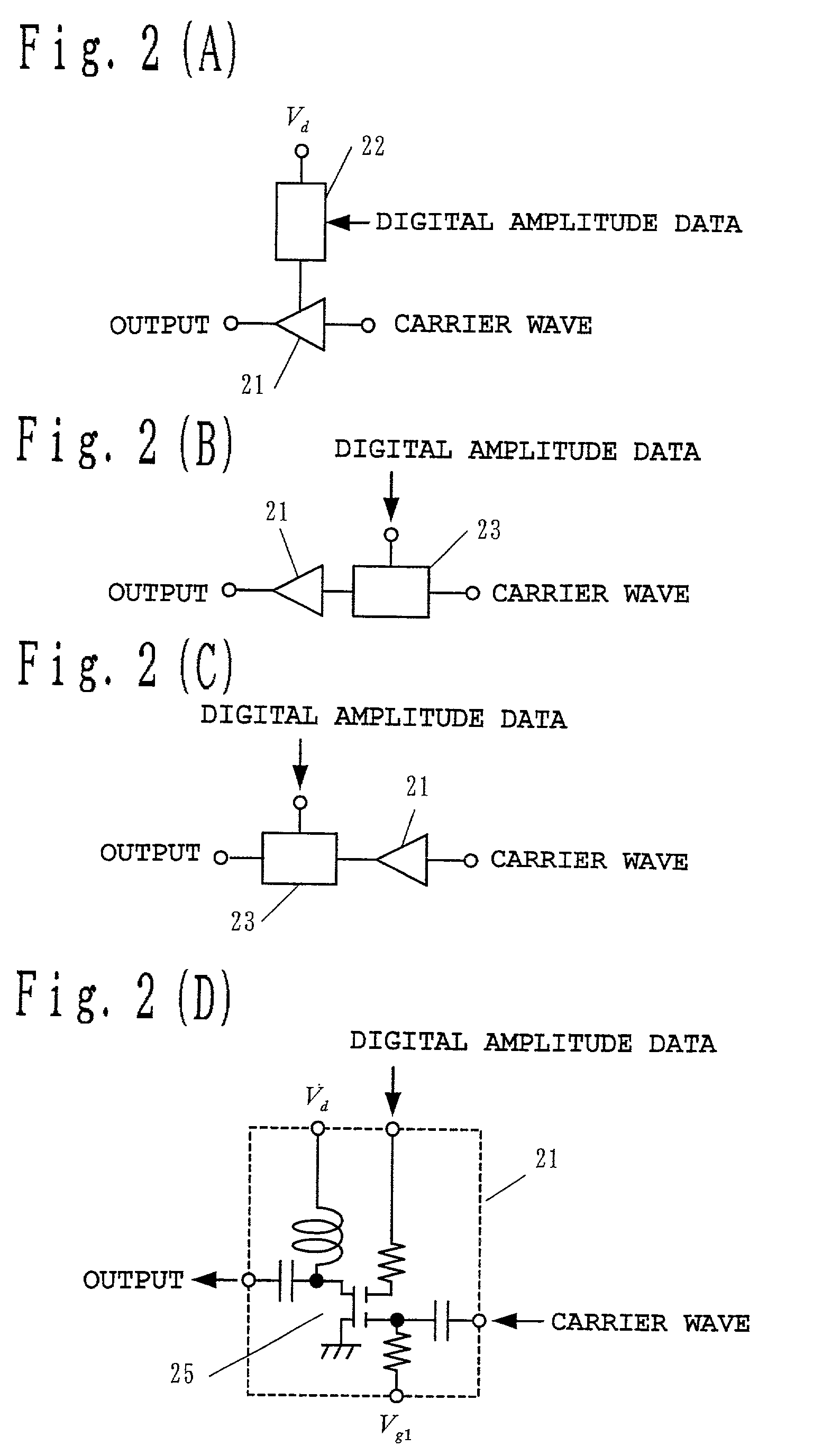
[0086]The amplitude modulator...

embodiment 2

[0131]FIG. 9 shows another embodiment of a transmitting circuit apparatus according to the present invention. FIG. 9 shows the configuration corresponding to the case that a frequency modulator and an amplitude modulator of the transmitting circuit apparatus in FIG. 1 are connected with an optical fiber. Since the contents shown in FIGS. 2 to 7 are applicable similarly, detailed description will be omitted. In addition, FIG. 9 shows a data generator 301, a frequency modulator 302, a sigma-delta modulator 303, E / O converters 304 and 305, a optical frequency synthesizer 306, a branching filter 307, O / E converters 308 and 309, an amplitude modulator 310, a band pass filter 311, an antenna 312, and an optical fiber 313. Outputs of the frequency modulator 302 and sigma-delta modulator 303 are converted into optical signals with E / O converters 304 and 305, respectively. The E / O converters 304 and 305 are laser diodes, and output light whose wavelengths differ from each other.

[0132]Frequen...


PUM


Abstract

A transmitting circuit apparatus hasa frequency modulator that performs frequency modulation of a carrier wave with frequency modulation data and outputs the frequency-modulated carrier wave;a sigma-delta modulator which performs sigma delta modulation of amplitude modulation data; andan amplitude modulator that performs amplitude modulation of the frequency-modulated carrier wave with an output signal of the sigma-delta modulator and outputs the amplitude-modulated carrier wave.

Description

BACKGROUND OF THE INVENTION[0001]1. Field of the Invention[0002]The present invention relates to a transmitting circuit apparatus and method used in radio communications.[0003]2. Related Art of the Invention[0004]In a transmitting circuit apparatus used in a digital radio communication using modulation techniques such as QPSK, it is common to use an orthogonal modulator as a modulator. The basic configuration of a conventional transmitting circuit apparatus is shown in FIG. 14. That is, FIG. 14 shows an orthogonal modulator 403, a band pass filter 404, an IQ signal generator 405, a local oscillator 406, a phase shifter 407, mixers 408 and 409, a synthesizer 410, and a power amplifier 411.[0005]The IQ signal generator 405 inputs digital data to divide it into two lines, and generates a baseband I signal and a baseband Q signal, which are analog signals, from respective lines to output the signals to an orthogonal modulator 403 respectively.[0006]The orthogonal modulator 403 comprises...

Claims


Application Information

Patent Timeline
Patent Type & Authority Patents(United States)
IPC IPC(8): H04B10/00H03F3/24H04L27/36
CPCH03F3/24H04L27/361H03F2200/331
Inventor ADACHI, HISASHIIIDA, MASANORIASAKURA, HIROYUKI
Owner PANASONIC CORP
Why Eureka
Try Eureka