Multi-axis capacitive accelerometer

a capacitive accelerometer and multi-axis technology, applied in the field of capacitive accelerometers, can solve the problems of poor cross-axis sensitivities, affecting the performance of cross-axis sensitivity seriously, poor linearity of the accelerometer, etc., to improve the linearity of sensing and eliminate linear shift in rotation

Active Publication Date: 2010-05-20
IND TECH RES INST
View PDF36 Cites 84 Cited by
  • Summary
  • Abstract
  • Description
  • Claims
  • Application Information

AI Technical Summary

Benefits of technology

[0010]Accordingly, the aforementioned multi-axis capacitive accelerometer is provided with a plurality of proof mass disposed inside a structure layer, wherein the proof mass are adapted to rotate symmetrically along a central axis of the structure layer. The proof masses are symmetrical structures themselves to eliminate linear shift in rotation when sustaining a force and thus improve the linearity of sensing. Furthermore, when the second proof mass and the third proof mass rotate as sustaining a force, components of force in the first direction and the second direction goes counterbalanced by one another to prevent interference for sensing the in-plane acceleration.

Problems solved by technology

The design likes this will cause cross-axis sensitivities poor.
This may affect the performance of cross-axis sensitivity seriously.
In addition, the motion of the proof mass for sensing Z-axis acceleration disclosed by U.S. Pat. No. 6,845,670 may be a combination of rotation and translation, and this may results in poor linearity of the accelerometer.
U.S. Pat. No. 7,258,012 discloses another accelerometer design with one sensing structure, but the motion of its Z-axis proof mass may also lead the Z-axis output with poor linearity.

Method used


Image

  • Multi-axis capacitive accelerometer
  • Multi-axis capacitive accelerometer
  • Multi-axis capacitive accelerometer

Examples


Embodiment Construction

[0021]Reference will now be made in detail to the present embodiments, examples of which are illustrated in the accompanying drawings. Wherever possible, the same reference numbers are used in the drawings and the description to refer to the same or like parts.

[0022]For resolving the problem in sensitivity and linearity of the conventional three-axis accelerometer and conforming the requirement of miniaturization, a multi-axis capacitive accelerometer capable of eliminating mutual interference of acceleration sensing in different axes is provided to achieve high sensitivity and linearity.

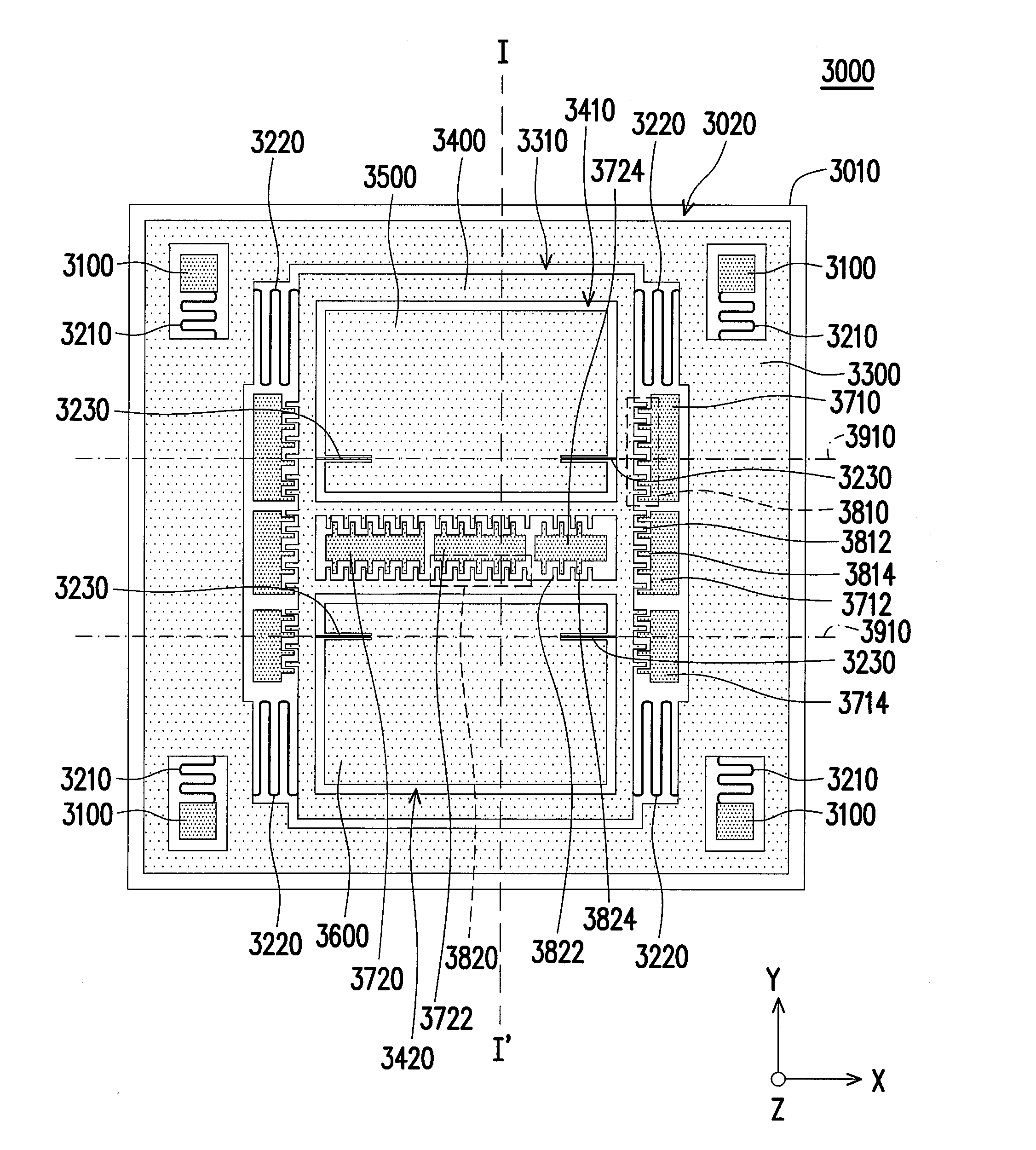
[0023]FIG. 4 shows a top view of a multi-axis capacitive accelerometer according to further another embodiment. FIG. 5 is a sectional view of the multi-axis capacitive accelerometer illustrated in FIG. 4 along line I-I′. Referring to FIG. 4 and FIG. 5, the multi-axis capacitive accelerometer 3000 comprises a substrate 3010 and a structure layer 3020. The substrate 3010 has a plurality of sensing ele...


PUM


Abstract

A multi-axis accelerometer is consisted of a substrate with sensing electrodes and a structure layer. The structure layer includes anchor bases fixed on the substrate. A first proof mass is disposed over the substrate and has a first opening and a second opening symmetric to each other. The first proof mass is suspended to the anchor bases. Fixed sensing blocks are disposed on the substrate, and capacitors are formed between each fixed sensing block and the first proof mass for sensing acceleration along two in-plane directions. A second proof mass and a third proof mass are disposed in the first opening and the second opening and are asymmetrically suspended. Separate electrodes are disposed on the substrate and form two differential capacitors with the second proof mass and the third proof mass for sensing the out-of-plane acceleration.

Description

CROSS-REFERENCE TO RELATED APPLICATION[0001]This application claims the priority benefit of U.S. provisional application Ser. No. 61 / 115,546, filed on Nov. 18, 2008, all disclosures are incorporated therewith. This application also claims the priority of Taiwan applications serial no. 97148843 and 97151113, filed on Dec. 15, 2008 and Dec. 26, 2008. The entirety of each of the above-mentioned patent applications is hereby incorporated by reference herein and made a part of this specification.BACKGROUND[0002]1. Technical Field[0003]The disclosure relates to an accelerometer which is manufactured by Micro Electro Mechanical System (MEMS) technology and has the capability of sensing two axes or three axes acceleration.[0004]2. Description of Related Art[0005]Many non-military applications require accelerometer with the ability to sense acceleration along three mutually orthogonal axes. For the applications in modern consumer electronic devices, the size and cost of a multi-axis accelero...

Claims


Application Information

Patent Timeline
Patent Type & Authority Applications(United States)
IPC IPC(8): G01P15/125
CPCG01P15/125G01P2015/0814G01P15/18G01P2015/082G01P2015/0831
Inventor HSU, YU-WENCHEN, SHEAHCHIEN, HSIN-TANG
Owner IND TECH RES INST
Why Eureka
Try Eureka