Negative feedback amplifier and method of controlling loop gain thereof

a negative feedback and amplifier technology, applied in the field of negative feedback amplifiers, can solve the problems of increasing the leakage power of the transmitted frequency band to the adjacent channels, increasing the probability of oscillation when the transmission frequency is changed, and increasing the probability of oscillation. to occur, the effect of increasing the leakage power and reducing the distortion

Inactive Publication Date: 2005-09-06
KOKUSA ELECTRIC CO LTD
View PDF10 Cites 25 Cited by
  • Summary
  • Abstract
  • Description
  • Claims
  • Application Information

AI Technical Summary

Benefits of technology

[0024]In the negative feedback amplifier shown in FIG. 4, the loop gain (=A·β) varies with the change of the gain A of the amplifier. Therefore, when the gain A of the amplifier is decreased, the distortion reducing effect is degraded, leading to the increase of the leakage power of the transmitted frequency band to the adjacent channels. On the contrary, when the gain A of the amplifier is increased, the phase margin or gain margin of the loop decreases, thus increasing the probability of oscillation when the transmission frequency is changed or when the radio equipment starts to operate. The factors to change the gain can be considered as irregular component characteristics, secular variation, and temperature change, and these factors deteriorate the transmission characteristics.

Problems solved by technology

Therefore, when the gain A of the amplifier is decreased, the distortion reducing effect is degraded, leading to the increase of the leakage power of the transmitted frequency band to the adjacent channels.
On the contrary, when the gain A of the amplifier is increased, the phase margin or gain margin of the loop decreases, thus increasing the probability of oscillation when the transmission frequency is changed or when the radio equipment starts to operate.
However, if the gain A of the amplifier is too large, oscillation is likely to occur.

Method used


Image

  • Negative feedback amplifier and method of controlling loop gain thereof
  • Negative feedback amplifier and method of controlling loop gain thereof
  • Negative feedback amplifier and method of controlling loop gain thereof

Examples


Embodiment Construction

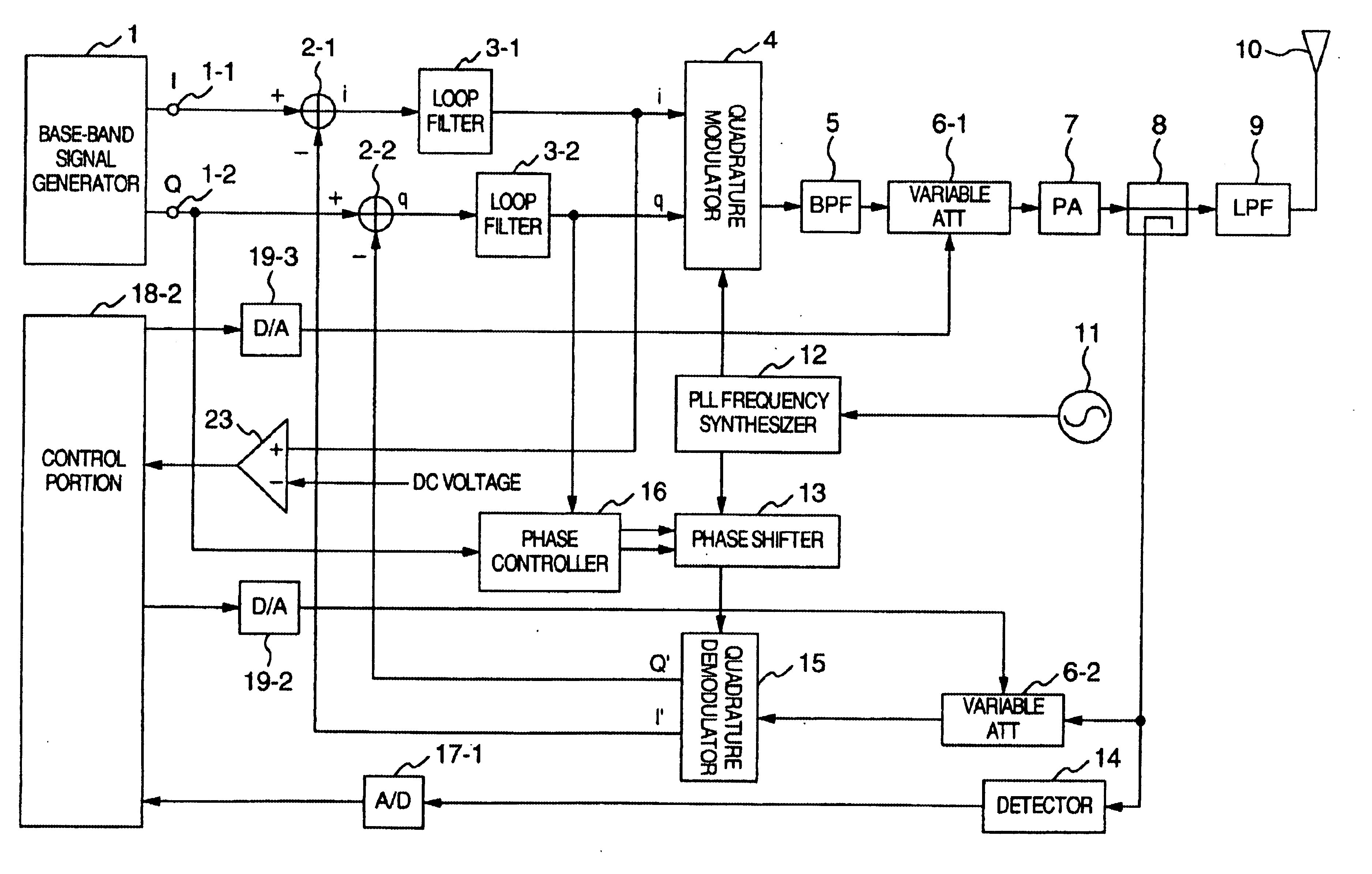
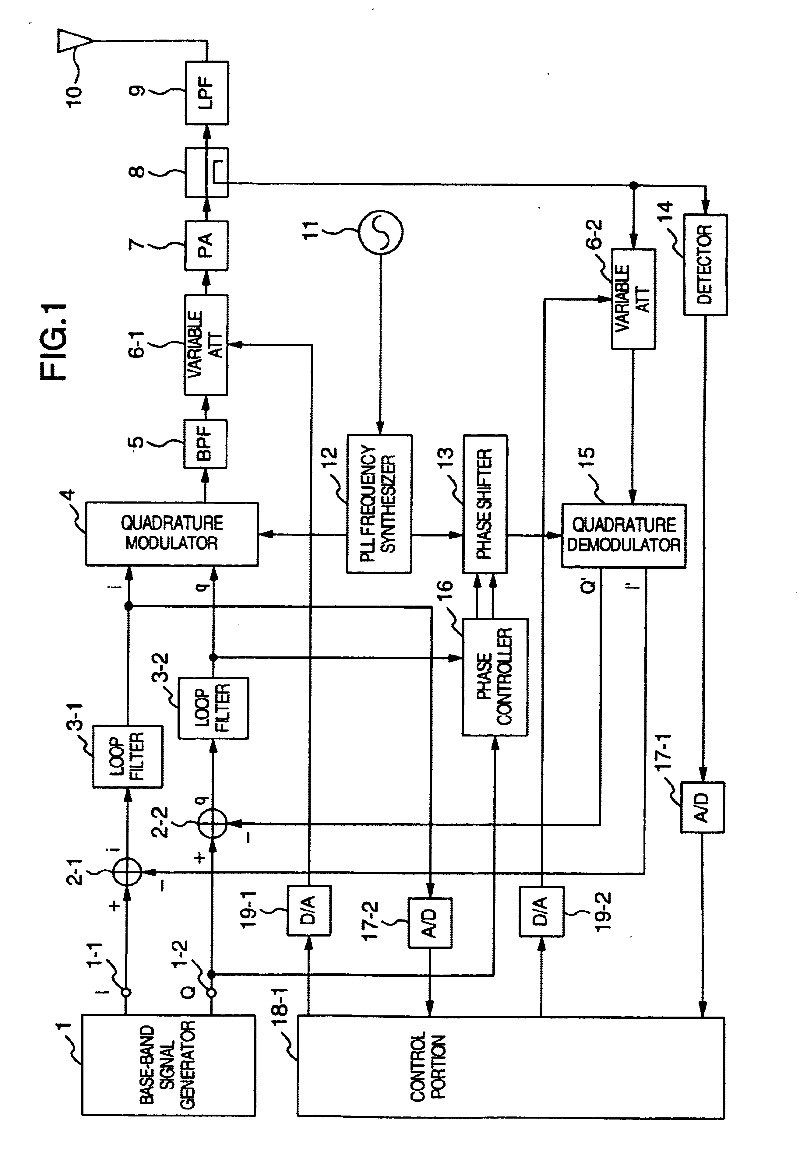
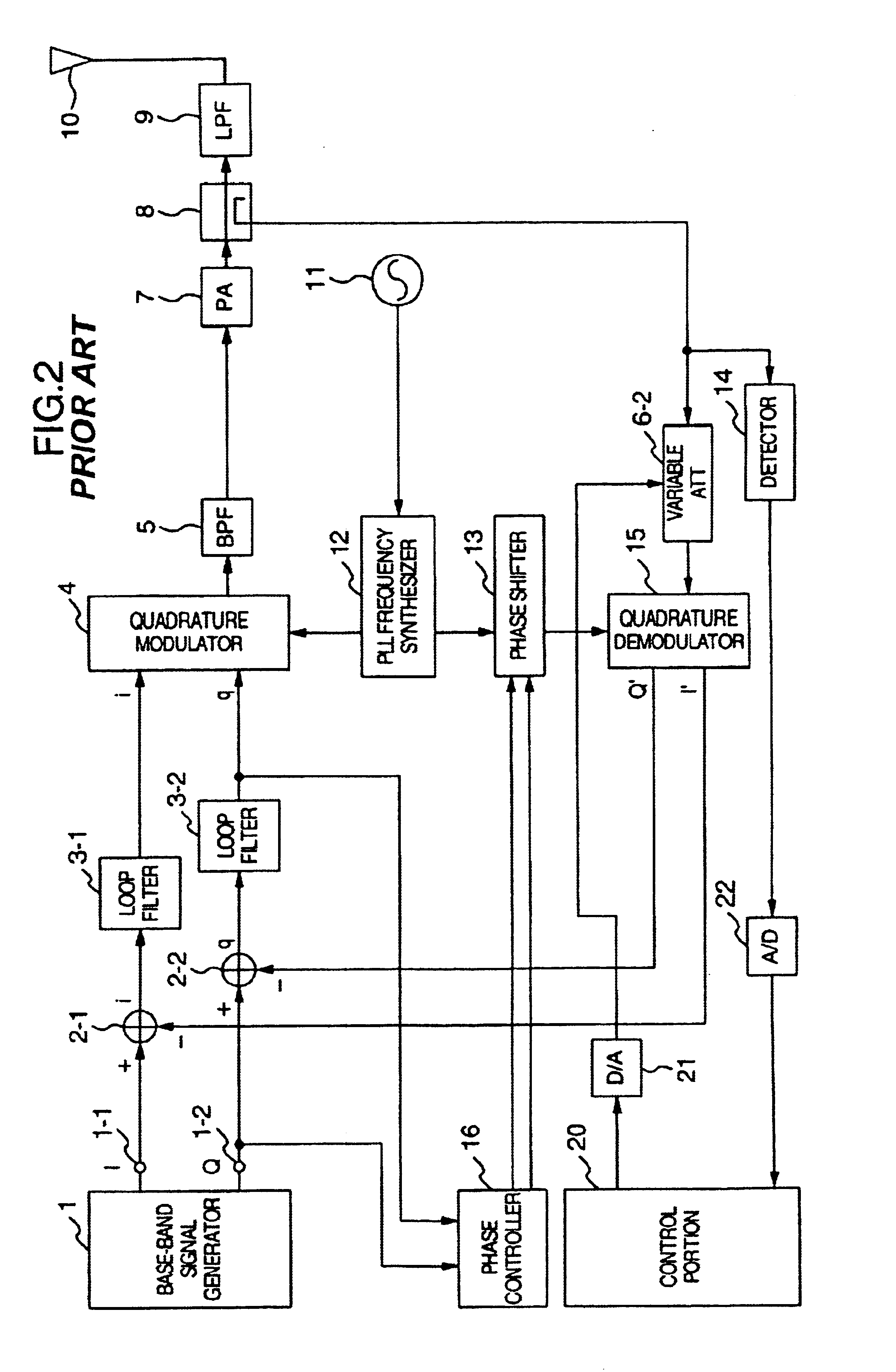
[0041]The operation principle of an embodiment of a negative feedback amplifier according to the invention will be described with reference to FIGS. 6, 7 and 8. FIGS. 6-8 are block diagrams of the constructions of models of a transmitter provided to describe the operation of the invention. FIGS. 6-8 are provided for explaining an operation of maintaining a loop gain by variably controlling a signal level of an amplifier when the loop gain was changed due to change of gain in the amplifier by some causes. In FIGS. 6-8, the values of input-output gains (dB) and the values of output level (dBm) of the circuit blocks in order to show the change of the signal levels in the amplifier and the feedback path. FIG. 6 shows distributed gains of the elements in operation at a specified level, FIG. 7 shows gains distributed when the gain of the power amplifier is reduced 3 dB, and FIG. 8 shows the operation for the improvement of the loop gain according to the invention.

[0042]The negative amplif...


PUM


Abstract

A negative feedback amplifier has input portions for receiving input signals, adder circuits, a quadrature modulator for performing a quadrature modulation on outputs of the adder circuits, a first signal level variable control circuit for adjusting a level of an output signal from the quadrature modulator, an amplifier circuit for amplifying an output of the first signal level variable control circuit, a feedback circuit for negative feedbacking an output of the negative feedback circuit to the adder circuit, and a second control circuit for controlling an adjusting amount in the first signal level variable control circuit based on the output signal levels of the adder circuits so that the output signal levels of the adder circuits becomes predetermined values. The feedback circuit includes a first control circuit for controlling a signal level of the feedback circuit so that the output signal level of the amplifier circuit becomes a predetermined value.

Description

CROSS-REFERENCE TO RELATED APPLICATIONS[0001]The present application relates to subject matters described in co-pending applications Ser. No. 09 / 672,688 filed on Sep. 29, 2000 and Ser. No. 09 / 768,469 filed on Jan. 25, 2001 assigned to the assignee of the present application. The disclosures of these applications are incorporated herein by reference.BACKGROUND OF THE INVENTION[0002]The present invention generally relates to power amplifiers, and particularly to compensation for the non-linear distortion of a power amplifier having a negative feedback circuit.[0003]Radio systems using a linear digital modulation system such as 16 QAM (Quadrature Amplitude Modulation) or π / 4QPSK (Quadrature Phase Shift Keying) absolutely need the compensation for the non-linear distortion of power amplifier circuit, and employ various types of non-linear compensation system (linearizer). Of the compensation systems, the linearizer of Cartesian loop negative feedback system has been used from a long tim...

Claims


Application Information

Patent Timeline
Patent Type & Authority Patents(United States)
IPC IPC(8): H03F1/32H03C3/00H03C3/40H03G3/30H03G3/20H04B1/04H04L27/00
CPCH03C3/406H03F1/3294H03F1/34H03F2200/57
Inventor YAMAMOTO, HIROYUKI
Owner KOKUSA ELECTRIC CO LTD
Why Eureka
Try Eureka