Zero insertion force card edge connector

a technology of edge connectors and zero insertion force, which is applied in the direction of coupling device connection, engagement/disengagement of coupling parts, printed circuits, etc., can solve the problems of electrical contact failure, soiled connection terminals of connectors, and more scrappings

Inactive Publication Date: 2011-04-12
FUJITSU LTD
View PDF13 Cites 11 Cited by
  • Summary
  • Abstract
  • Description
  • Claims
  • Application Information

AI Technical Summary

Benefits of technology

[0015]It is an object of the present invention to at least partially solve the problems in the conventional technology.

Problems solved by technology

The above conventional connectors, however, pose the following problems.
As a result, scrapings are produced more frequently to bring the cause of an electrical contact failure.
In a case of conventional connector-related structures disclosed in publication of patent applications, a connection terminal of a connector may be soiled due to frequent use or deterioration by aging, or scrapings may be produced between contact faces as a result of strong contact between the contact faces.
These structures, therefore, also pose a problem of the occurrence of such a trouble as contact failure.

Method used


Image

  • Zero insertion force card edge connector
  • Zero insertion force card edge connector
  • Zero insertion force card edge connector

Examples


first embodiment

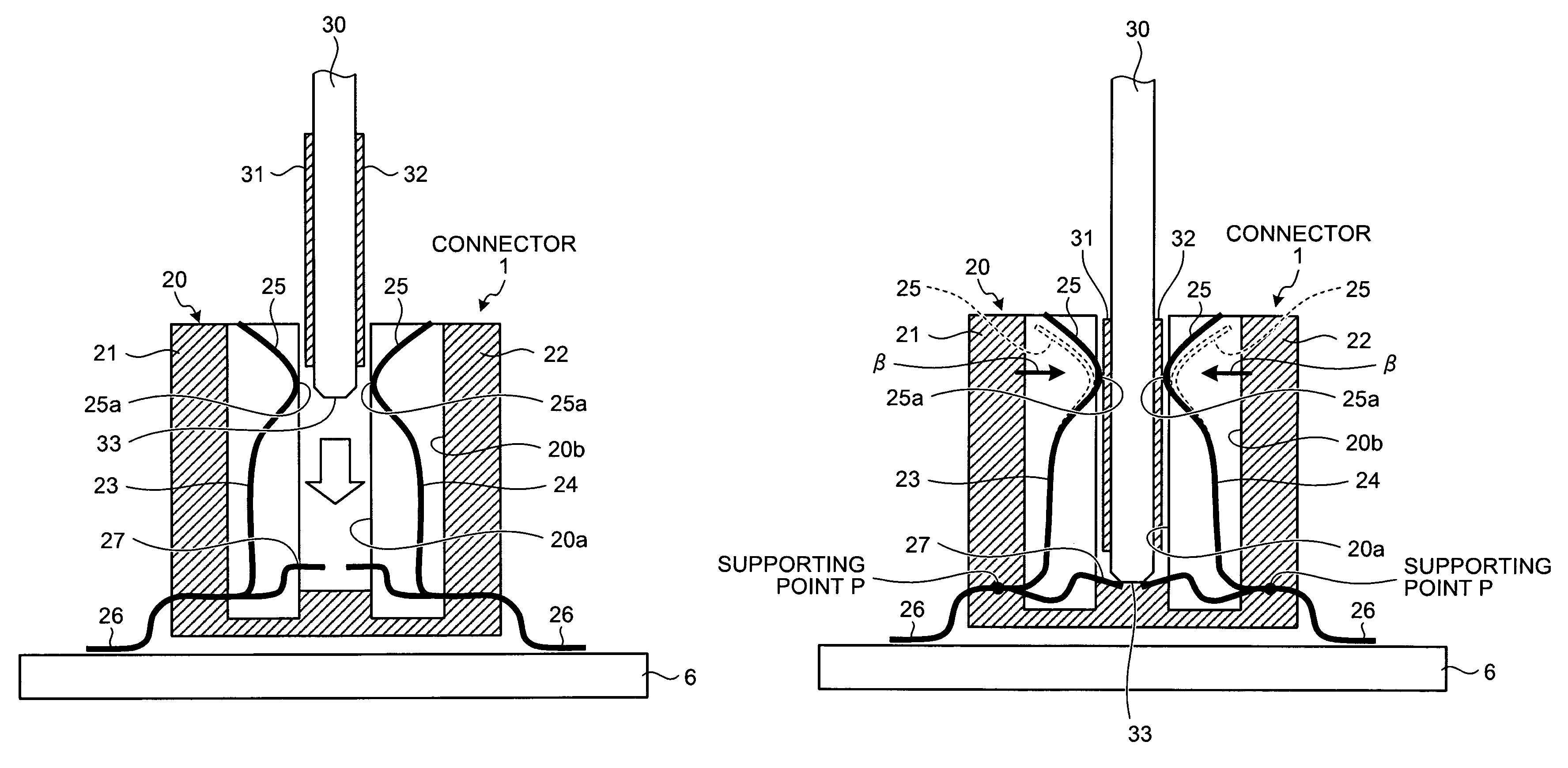
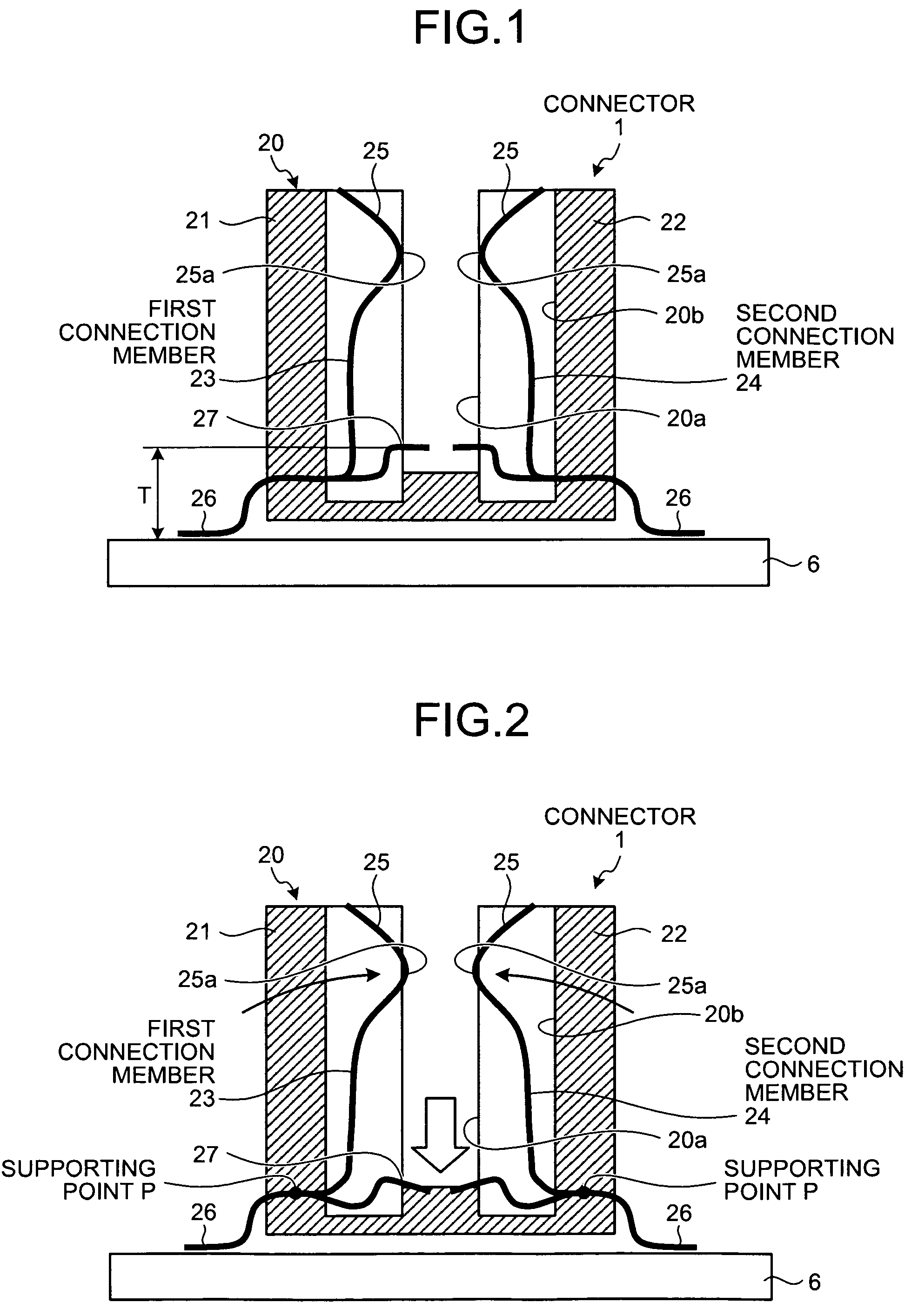
[0029]Exemplary embodiments of structures of a connector 1 according to the present invention will now be described in detail with reference to the accompanying drawings. FIG. 1 is a general configuration diagram of the interior of the connector 1 according to a FIG. 2 is an explanatory view of the operation state of a first connection member 23 and a second connection member 24.

[0030]In the first embodiment, a general configuration and features of the connector 1 will be described, and the detail of operation state of the connector 1 will then be described. The first embodiment to be described does not limit the present invention.

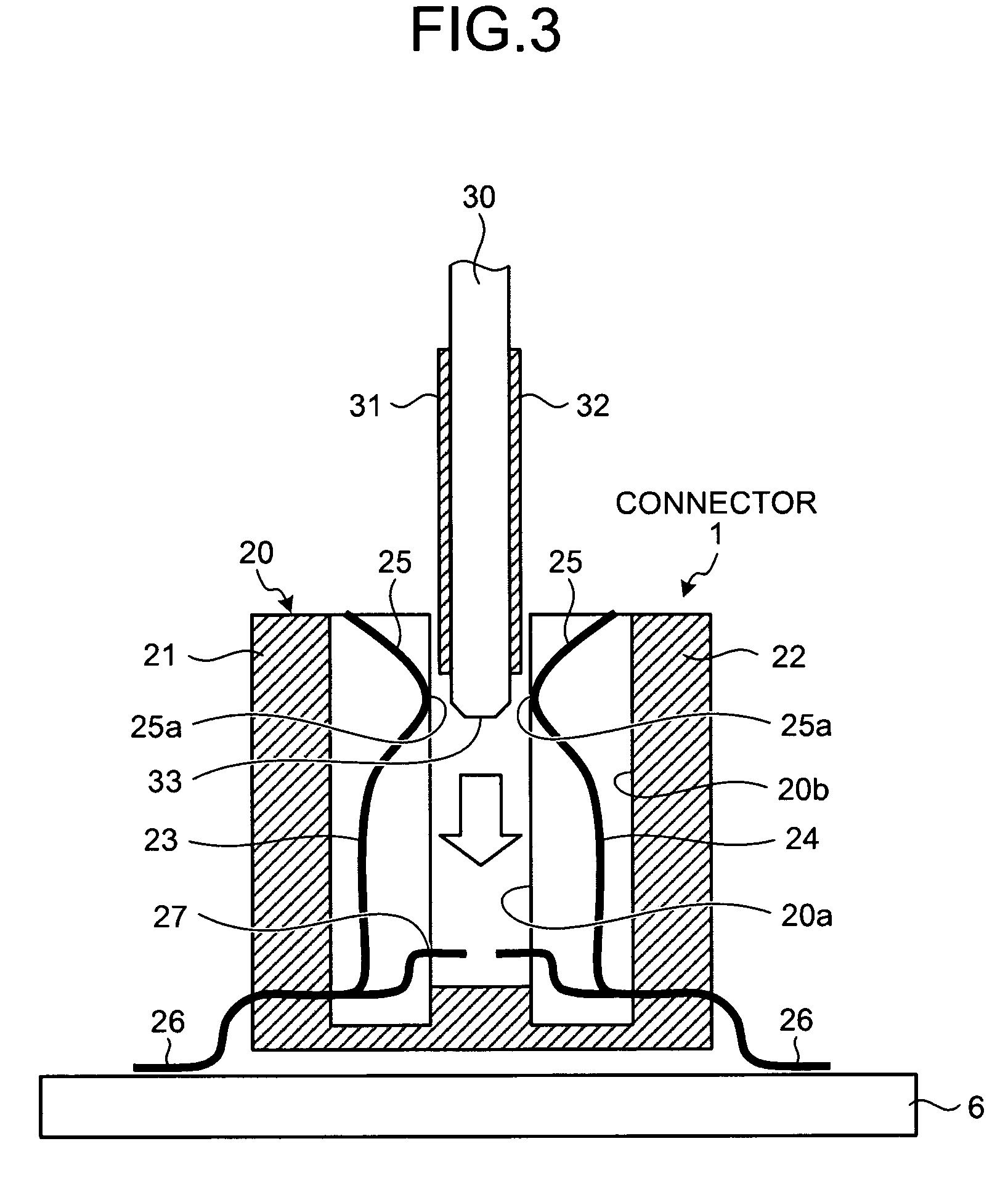
[0031]As shown in FIG. 1, according to the connector 1 of the first embodiment, contact members (first connection member 23 and second connection member 24) of the connector 1 that come in electrical contact with terminal units 31 and 32 (see FIG. 3) of a board module 30 each include a connection body 25 having a connection terminal 25a formed thereon, an...

second embodiment

[0045]The structure of the connector 1a of the second embodiment has a feature that the position of formation of press members 27a of the connector 1a is determined to be a given height T1 in correspondence to a press by the leading edge 33 (FIG. 5) of the board module 30 and deformation start timing at which the connection bodies 25 start deforming in response to the press to the press members 27a.

[0046]Specifically, as shown in FIG. 6, the height of the press members 27a and 27a of the first connection member 23 and the second connection member 24 disposed in the connector 1a is determined to be a given preset value (height T1) so that timing of a press to the press members 27a and 27a by the leading edge 33 of the board module 30 become earlier.

[0047]In the second embodiment, the height T1 of the press members 27a is determined to be greater than the height T of the press members 27 of the connector 1 of the first embodiment shown in FIG. 1 (height T1>height T). Because of this,...

third embodiment

[0051]The connector 1b of the third embodiment has a feature that the positions of press members 27, 27a, and 27b having a plurality of the first connection members 23 and the second connection members 24 of the connector 1b are determined to be heights different from each other in correspondence to timing of electrical connection made by contact between a plurality of the connection terminals 25a and 25a of the first and second connection members 23 and 24 and the terminal units 31 and 32 of the board module 30.

[0052]Specifically, as shown in FIG. 7, among the press members 27, 27a and 27b of the plurality of first connection members 23 and second connection members 24 disposed in the connector 1b, the press members 27 are set at the height T, the press members 27a are set at the height T1, and the press members 27b are set at the height T2 so that the positions of the press members 27, 27a, and 27b are different from each other according to the determined heights (height T12).

[005...


PUM


Abstract

A connector includes a first connection member and a second connection member that come in electrical contact with terminal units of a board module. The first and second connection members have connection bodies with connection terminal units formed thereon, and press members that at the time of setting the board module, cause the connection terminals of the connection bodies to deform toward the terminal units of the board module and come in contact with the terminal units when the press members comes in contact with the leading edge of the board module.

Description

CROSS-REFERENCE TO RELATED APPLICATIONS[0001]This application is based upon and claims the benefit of priority of the prior Japanese Patent Application No. 2008-106145, filed on Apr. 15, 2008, the entire contents of which are incorporated herein by reference.BACKGROUND[0002]1. Field[0003]The present invention relates to a connector that electrically connects a printed wiring board (board module) used in electric equipment, etc., and more particularly, to a connector capable of preventing a contact failure between a contact terminal of a board module and a contact member of a connector and of improving the reliability of a connector for a long period.[0004]2. Description of the Related Art[0005]Conventionally, when a board module carrying a semiconductor component, etc., is connected electrically, a card edge connector, etc., having a contact member connected freely to a contact terminal of the board module has been used.[0006]The structure of a conventional connector 1′ will be desc...

Claims


Application Information

Patent Timeline
Patent Type & Authority Patents(United States)
IPC IPC(8): H01R12/00
CPCH01R12/87
Inventor MASUDA, YASUSHI
Owner FUJITSU LTD
Why Eureka
Try Eureka