
Notebook optical disc drive capable of generating a pseudo eject signal

a technology of optical disc drives and notes, applied in the field of optical disc drives, can solve the problems of unnecessarily consuming internal electric power of approximately 200 mw to 400 mw, and the addition of a power supply switch is not very desirable, and the period of odd operation is extremely short compared with the usage time of the entire note p

Active Publication Date: 2011-04-19
LENOVO PC INT
View PDF9 Cites 12 Cited by
  • Summary
  • Abstract
  • Description
  • Claims
  • Application Information

AI Technical Summary

Benefits of technology

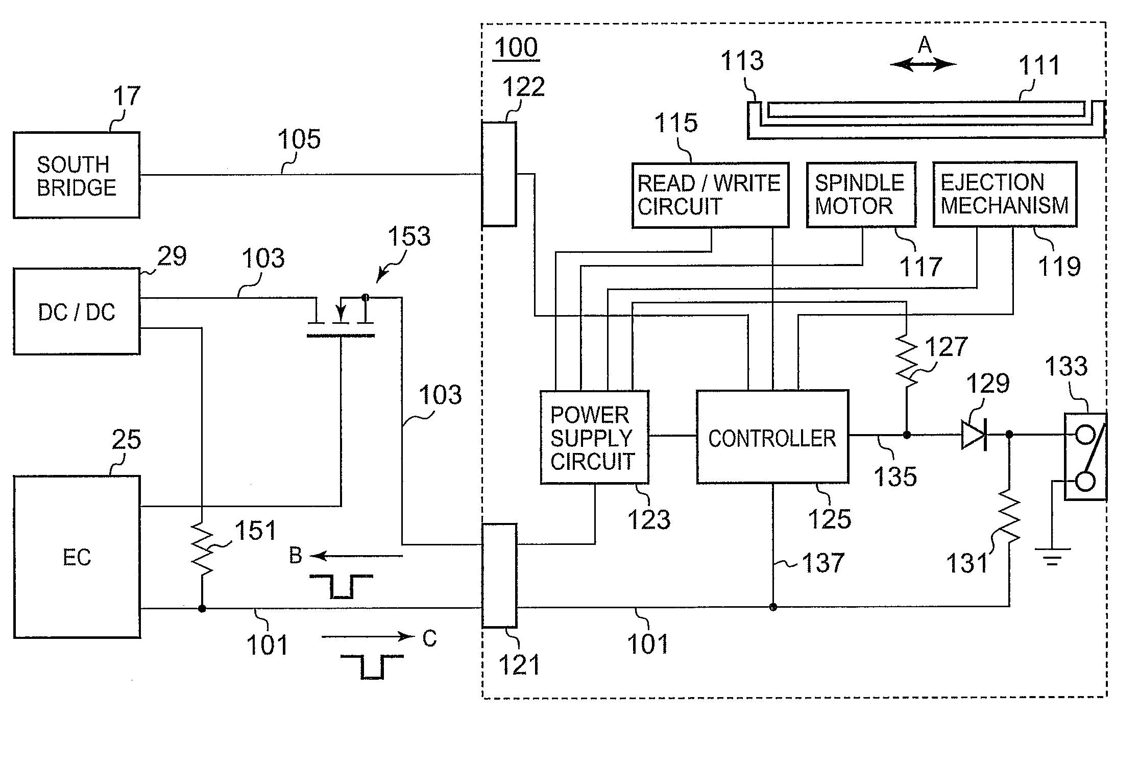
"The present invention is for an optical disc drive that has a mechanism to eject the tray that holds the disc. The drive includes an automatic return-type eject switch, a drive controller, and an eject controller. The eject switch sends a signal to the drive controller to eject the tray, and the controller supplies power to the drive and sends a signal to the eject controller to eject the tray after a set amount of time has passed. The technical effect of this invention is to provide a more efficient and reliable mechanism for ejecting the tray in an optical disc drive."

Problems solved by technology

Since the ODD of a note PC is typically used only for reading / writing data from / to a disc recording medium and is not used for other purposes, the period when the ODD is actually operating is extremely short compared with the usage time of the entire note PC.
Thus, if electric power is supplied to the ODD even when it is not being used, electric power of approximately 200 mW to 400 mW is unnecessarily consumed internally.
However, since the provision of a power supply switch may lead to cost increase and may impose an extra operation on the user, the addition of the power supply switch is not very desirable.
However, the ODD may not recognize the eject signal when the power supply is not input thereto, and at a time when the power supply is input to the ODD, the eject switch may return to its original state so that the eject signal disappears.

Method used


Image

  • Notebook optical disc drive capable of generating a pseudo eject signal
  • Notebook optical disc drive capable of generating a pseudo eject signal
  • Notebook optical disc drive capable of generating a pseudo eject signal

Examples


Embodiment Construction

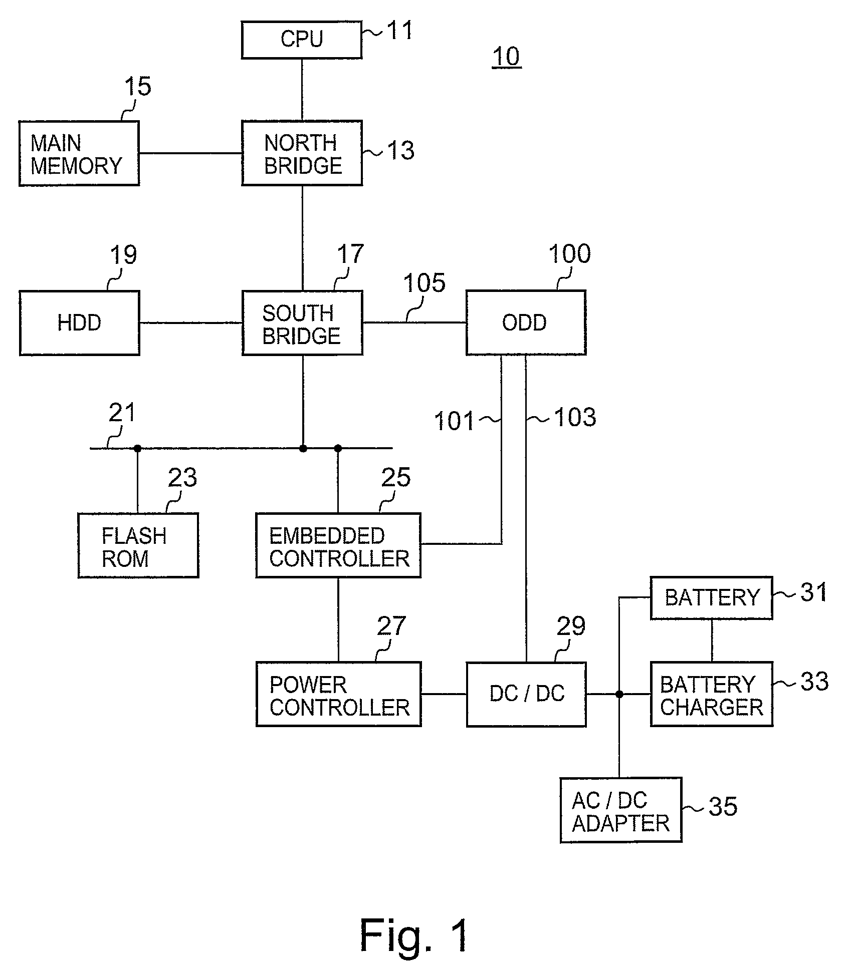
[0017]Referring now to the drawings and in particular to FIG. 1, there is depicted a block diagram of a note PC 10. A CPU 11 is an arithmetic processing device performing the central function of the note PC 10 and executes an operating system (OS), a BIOS, a device driver, or application programs. The CPU 11 controls a north bridge 13 and devices connected to the north bridge 13 via various buses. The north bridge 13 has a memory controller function for controlling an operation of accessing a main memory 15, a data buffer function for absorbing a difference in a data transfer rate between the CPU 11 and other device.

[0018]The main memory 15 is a random access memory used as a read area of programs executed by the CPU 11 and as a work area to which processed data are written. A south bridge 17 is connected to the north bridge 13, a hard disc device (HDD) 19, and an optical disc drive (ODD) 100. The south bridge 17 has integrated therewith an IDE controller serving as an interface of ...


PUM

PropertyMeasurementUnit
electric poweraaaaaaaaaa
timeaaaaaaaaaa
initialization timeaaaaaaaaaa

Abstract

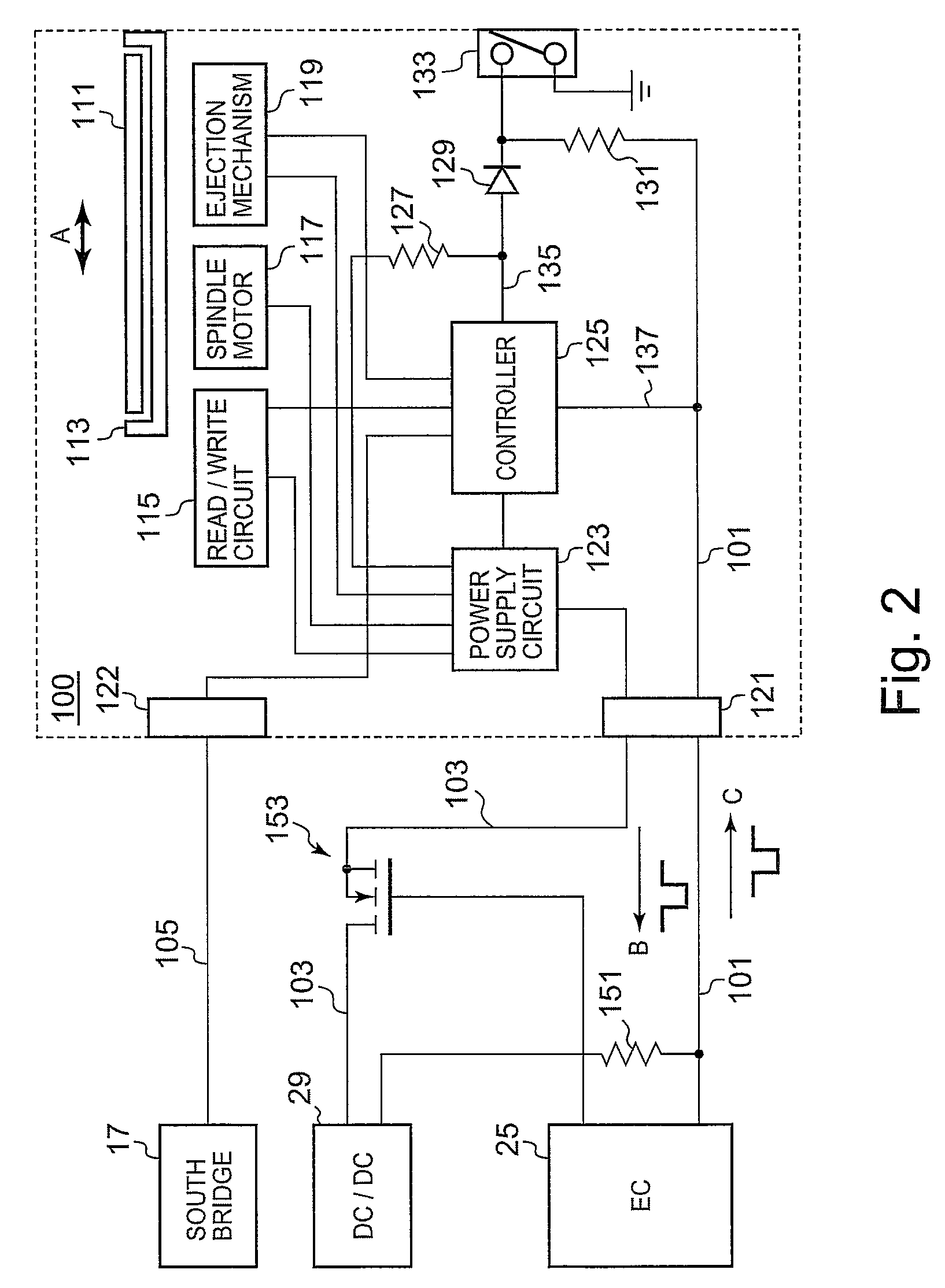
A optical disc drive is disclosed. The optical disc drive includes a housing and a tray configured to accommodate a disc therein. The optical disc drive also includes an automatic return-type eject switch, a drive controller, and an eject controller. Mounted in the housing, the automatic return-type eject switch is configured to generate an eject signal. In response to the eject signal, the drive controller ejects the tray. In response to the eject signal, the eject controller supplies an electric power to the optical disc drive, and transmits a pseudo eject signal to the drive controller to eject the tray by way of a line through which the eject signal has been transferred after a predetermined time period from the supply of the electric power has lapsed.

Description

PRIORITY CLAIM[0001]The present application claims benefit of priority under 35 U.S.C. §§120, 365 to the previously filed Japanese Patent Application No. JP2008-024814 entitled, “Tray ejecting system of optical disc drive and computer” with a priority date of Feb. 5, 2008, which is incorporated by reference herein.BACKGROUND OF THE INVENTION[0002]1. Technical Field[0003]The present invention relates to optical disc drives in general, and in particular to a method for achieving power savings on an optical disc drive.[0004]2. Description of Related Art[0005]A notebook personal computer (note PC) commonly includes an optical disc drive (ODD). A disc recording medium can be loaded into and unloaded from an ODD. Since the ODD of a note PC is typically used only for reading / writing data from / to a disc recording medium and is not used for other purposes, the period when the ODD is actually operating is extremely short compared with the usage time of the entire note PC. Thus, if electric po...

Claims


Application Information

Patent Timeline
Patent Type & Authority Patents(United States)
IPC IPC(8): G11B21/08
CPCG11B17/056G06F1/266
Inventor YAMAZAKI, MITSUHIROTSUKAMOTO, YASUMICHITAKAHASHI, TOSHIKI
Owner LENOVO PC INT
Learn More