System, method and computer readable media for reducing wheel sliding on a locomotive

a technology of computer readable media which is applied in the direction of motor/generator/converter stopper, dynamo-electric converter control, instruments, etc., can solve the problems that the inductive speed sensor typically exhibits poor performance at low locomotive speed, and achieves the effect of reducing wheel sliding, reducing wheel sliding, and reducing wheel sliding

Inactive Publication Date: 2011-04-19
GE GLOBAL SOURCING LLC
View PDF10 Cites 4 Cited by
  • Summary
  • Abstract
  • Description
  • Claims
  • Application Information

AI Technical Summary

Problems solved by technology

For example, inductive speed sensors typically exhibit poor performance at low locomotive speeds, including low signals in response to rotation of the locomotive axles at such low locomotive speeds.

Method used


Image

  • System, method and computer readable media for reducing wheel sliding on a locomotive
  • System, method and computer readable media for reducing wheel sliding on a locomotive
  • System, method and computer readable media for reducing wheel sliding on a locomotive

Examples


Embodiment Construction

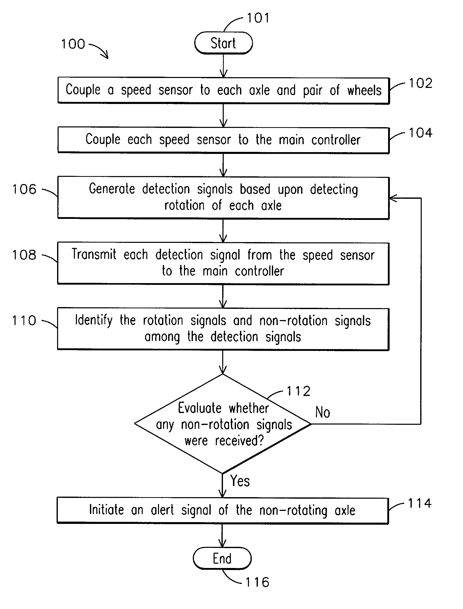
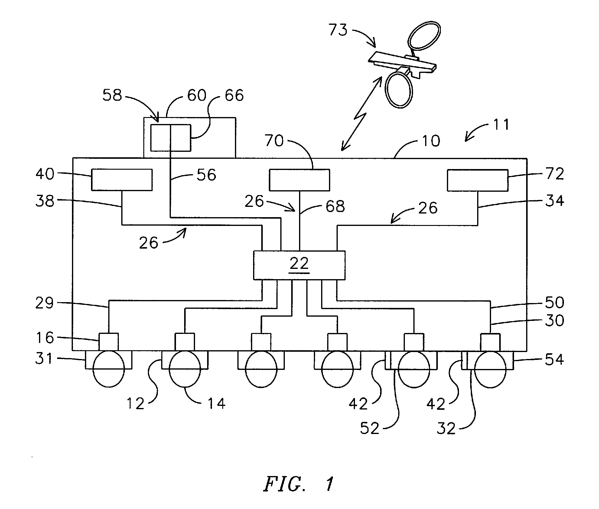
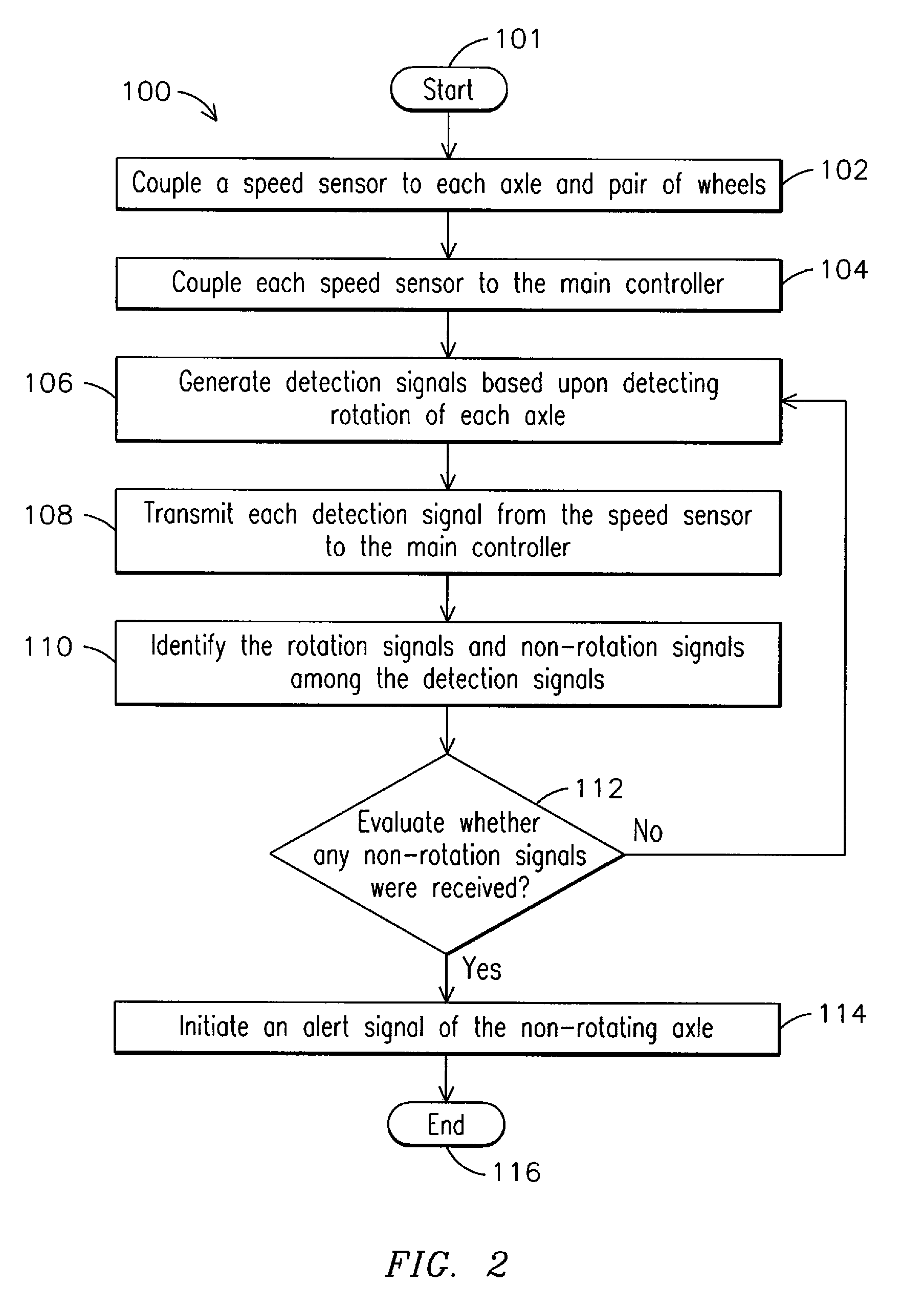
[0014]FIG. 1 illustrates a locomotive 10 including an embodiment of a system 11 for reducing wheel sliding on a locomotive. The system 11 is illustratively for reducing wheel sliding on a locomotive 10 traveling at a locomotive speed and including a plurality of axles 12 and respective pair of wheels 14. The system 11 illustratively includes a speed inferring system 16 coupled to at least one axle 12 and respective pair of wheels 14 to detect rotation of each axle and generate a detection signal 29,30 based upon detecting rotation of each axle 12. Although FIG. 1 illustrates a speed inferring system 16 coupled to each axle 12, the speed inferring system may just be coupled to the parking brake axles 52,54, as discussed below. Each detection signal 29,30 includes one of a speed signal 29 indicative of locomotive speed, which may be indicative of a rotating axle 31, and a non-rotating signal 30 indicative of a non-rotating axle 32. The speed signal 29 may include a rotating signal 29 ...


PUM


Abstract

A system for reducing wheel sliding on a locomotive is provided for a locomotive including a plurality of axles. The system includes one or more speed inferring systems coupled to each axle to detect rotation of each axle and generate detection signals based upon detecting rotation of each axle. The detection signals include one of speed signals indicative of locomotive speed and non-rotating signals indicative of a non-rotating axle. More particularly, a main controller is coupled to each speed inferring system and is responsive to each detection signal. The main controller identifies non-rotating signals of the detection signals to initiate one or more alert signals of one or more respective non-rotating axles of the plurality of axles. Additionally, the main controller is coupled to an operator panel to alert a locomotive operator of an applied status of a locomotive parking brake in response to the alert signal.

Description

FIELD OF THE INVENTION[0001]The present invention relates to locomotives, and more particularly, to a system, method and computer readable media for reducing wheel sliding on a locomotive.BACKGROUND OF THE INVENTION[0002]Various types of speed sensors have been employed to detect rotation of locomotive axles and wheels. For example, inductive speed sensors typically exhibit poor performance at low locomotive speeds, including low signals in response to rotation of the locomotive axles at such low locomotive speeds.[0003]Accordingly, there is a need for a system and method for detecting and differentiating a locked locomotive axle at low locomotive speeds due to multiple reasons. The inventors have recognized that such a system and method should involve monitoring the rotation of the locomotive axles at an initial low speed, so to avoid the forming of a flat spot which requires truing of the locomotive wheel.BRIEF DESCRIPTION OF THE INVENTION[0004]In one embodiment of the present inv...

Claims


Application Information

Patent Timeline
Patent Type & Authority Patents(United States)
IPC IPC(8): G06F19/00
CPCB60L3/102B60T17/228B60T13/665B60L2240/30B60L2200/26
Inventor DAUM, WOLFGANGVERMA, RAJEEVWORDEN, BRET DWAYNESTEWART, JR., ROBERT J.KUMAR, AJITH KUTTANNAIR
Owner GE GLOBAL SOURCING LLC
Why Eureka
Try Eureka