Apparatus and method for backup control in a distributed flight control system

a flight control system and backup control technology, applied in the field of aircraft flight control systems, can solve the problems that the flight control system of smart actuators often fails to address the problem of generic fault in the transmission media or the command processing of the primary flight control system, and achieve the effect of not compromising

Active Publication Date: 2007-07-19
GULFSTREAM AEROSPACE CORP
View PDF61 Cites 118 Cited by
  • Summary
  • Abstract
  • Description
  • Claims
  • Application Information

AI Technical Summary

Benefits of technology

[0009]Embodiments of the invention may be configured to include two distributed flight control systems, a primary flight control system and a simple backup flight control system that are both independent and dissimilar. The primary control system may also be configured to monitor and insure the integrity of both systems during flight without compromising the simplicity and reliability in the backup flight control system. For example, a backup control system in accordance with embodiments of the invention may be very simple, without any direct monitoring functions, and the more complex primary flight control system may monitor the backup control system during normal operation to insure its availability. Embodiments of the invention may be used to eliminate the need for significant analysis and design efforts to verify dissimilarity between the primary control system and the backup control system. The backup control system may be implemented as an analog or programmable logic based control system or a software based control system.

Problems solved by technology

Despite the advancements of smart actuator control systems, the smart actuator flight control systems often fail to address the problem of a generic fault in the transmission media or the command processing of the primary flight control system.

Method used


Image

  • Apparatus and method for backup control in a distributed flight control system
  • Apparatus and method for backup control in a distributed flight control system
  • Apparatus and method for backup control in a distributed flight control system

Examples


Embodiment Construction

[0016]The present disclosure will now be described more fully with reference to the Figures in which various embodiments of the present invention are shown. The subject matter of this disclosure may, however, be embodied in many different forms and should not be construed as being limited to the embodiments set forth herein.

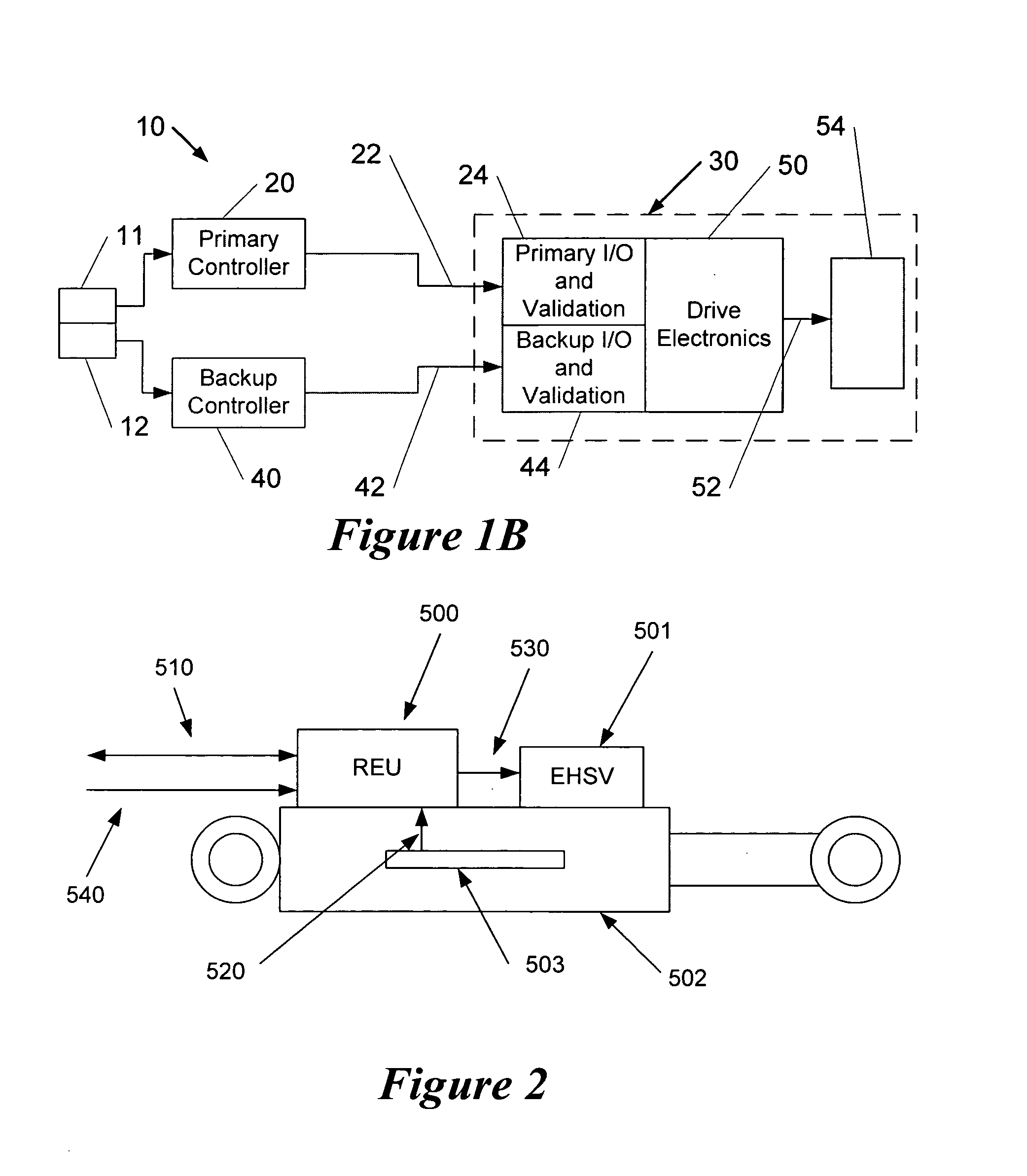
[0017]Embodiments of the invention are directed to a distributed flight control system configured to employ independent and dissimilar primary and backup flight control systems. The backup control system may be configured as a simplified or Minimum Acceptable Control (“MAC”) system, for example. Additionally, the primary flight control system may be configured to verify the integrity of the primary and backup flight control systems and transmission paths during use without endangering the independent and dissimilar characteristics of the backup control system.

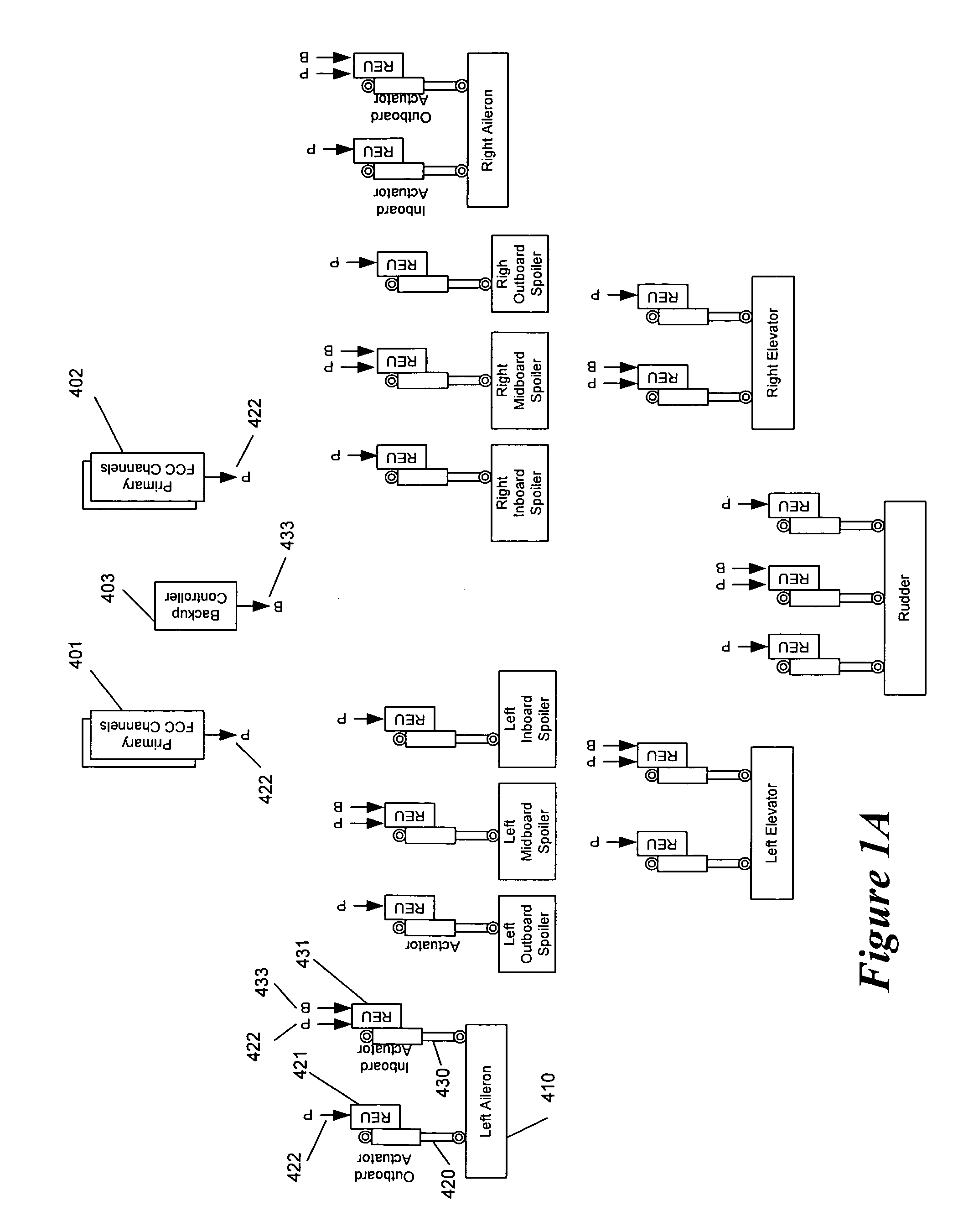
[0018]FIG. 1A schematically illustrates a sample distributed Fly-By-Wire control system having a primary ...


PUM


Abstract

Embodiments of the invention relate to a flight control system for controlling an aircraft during flight. The flight control system may include a primary controller configured to receive an input from a pilot and to output a primary control signal and a primary transmission path connected to the primary controller and configured to relay the primary control signal. The flight control system may also include a backup controller configured to receive the input from the pilot and to output a backup control signal and a backup transmission path connected to the backup controller and configured to relay the backup control signal. Additionally, the flight control system may include an actuator having a remote electronics unit configured to receive the primary control signal and the backup control signal and to determine if the primary control signal is available and valid. The remote electronics unit may be configured to output an actuator command based on the primary control signal if the primary control signal is available and valid and to output the actuator command based on the backup control signal if the primary control signal is unavailable or invalid.

Description

[0001]This application claims priority to co-pending U.S. Provisional Patent Application 60 / 759,028, filed Jan. 17, 2006, and entitled “Advanced Flight Control System Architecture,” which is assigned to the assignee of the present invention and is hereby incorporated by reference in its entirety. This application is related to co-pending U.S. Patent Application filed on Jan. 17, 2007, entitled “System and Method for an Integrated Backup Control System,” which is assigned to the assignee of the present invention and is hereby incorporated by reference in its entirety.FIELD OF THE INVENTION[0002]Embodiments of the invention relate generally to aircraft flight control systems and, more specifically, to the implementation of a redundant, backup control system for a distributed fly-by-wire (FBW) flight control system.BACKGROUND OF THE INVENTION[0003]With the rapid developments in aircraft technology, ever-increasing flight envelopes, and overall performance, the flight control systems im...

Claims


Application Information

Patent Timeline
Patent Type & Authority Applications(United States)
IPC IPC(8): G05D1/00
CPCB64C13/42Y02T50/44G05D1/0077B64C13/504B64C13/505Y02T50/40
Inventor HIRVONEN, JUKKA MATTI
Owner GULFSTREAM AEROSPACE CORP
Why Eureka
Try Eureka