Airbag and airbag device

a technology for airbags and devices, applied in the field of airbags, can solve the problems of increasing the cost of configuring an airbag device, the strap being tense,

Inactive Publication Date: 2011-04-26
TAKATA CORPORATION
View PDF28 Cites 42 Cited by
  • Summary
  • Abstract
  • Description
  • Claims
  • Application Information

AI Technical Summary

Benefits of technology

[0022]When this airbag is inflated, the connecting member is under tension between the near-occupant face of the airbag and the covering member and between the lower portion of the airbag and the covering member. This prevents the covering member from moving toward the outside of the airbag, and the covering member overlies the openable-closable vent hole, whereby the openable-closable vent hole closes or slightly opens. Thus, the discharge of the gas through the vent hole is regulated, and the airbag is quickly deployed.
[0049]In this embodiment, it is preferable that the fixed end of the covering member is connected to the airbag with the linear connected portion extending in a direction intersecting a direction connecting the fixed end and the free end of the covering member, and line segments connecting both ends of the linear connected portion and the constantly open vent hole substantially form a triangle with the foregoing elements as vertexes, the openable-closable vent hole residing within the triangle (the ninth embodiment). In this case, by providing the covering member with an outer shape substantially matching this triangle, the covering member having the minimum area can sufficiently cover the openable-closable vent hole.

Problems solved by technology

According to the publication, when the airbag is inflated, the near-occupant face and the away-from-occupant face of the airbag move away from each other, causing the strap to be under tension.
However, such an embodiment increases the cost of configuring an airbag device.

Method used


Image

  • Airbag and airbag device
  • Airbag and airbag device
  • Airbag and airbag device

Examples


Embodiment Construction

[0072]Embodiments of the present invention will now be described with reference to the drawings.

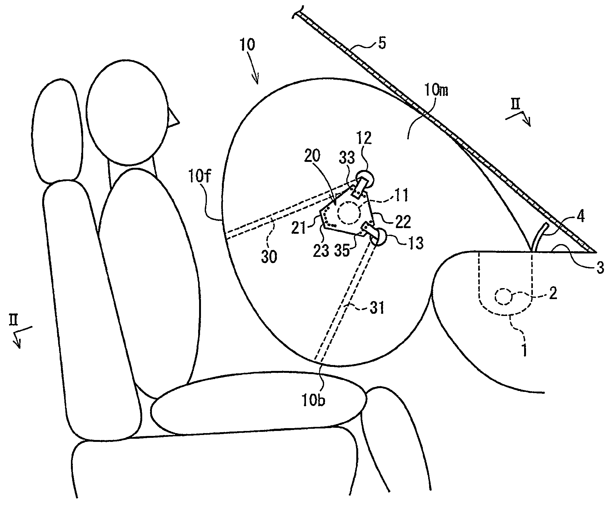
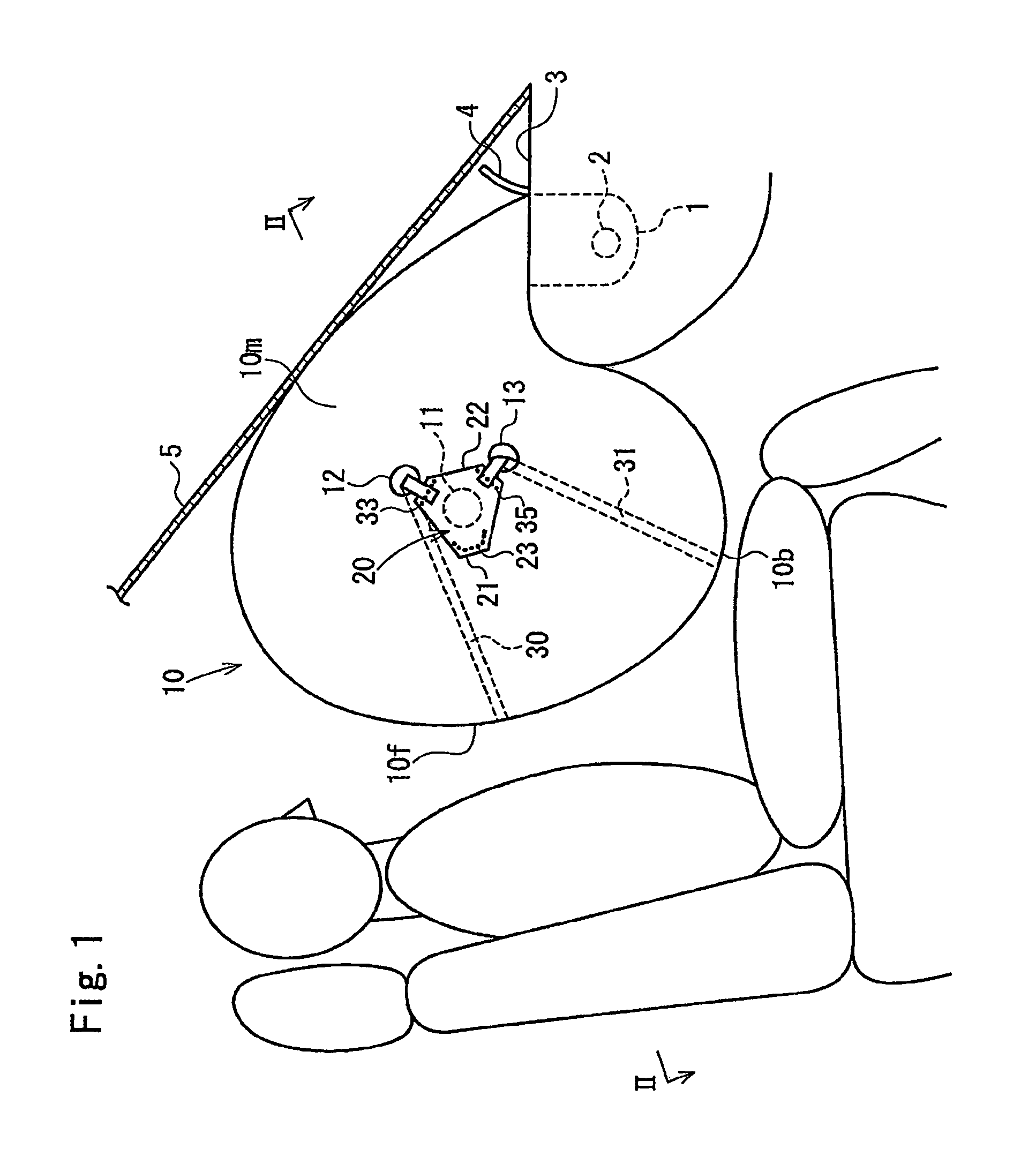
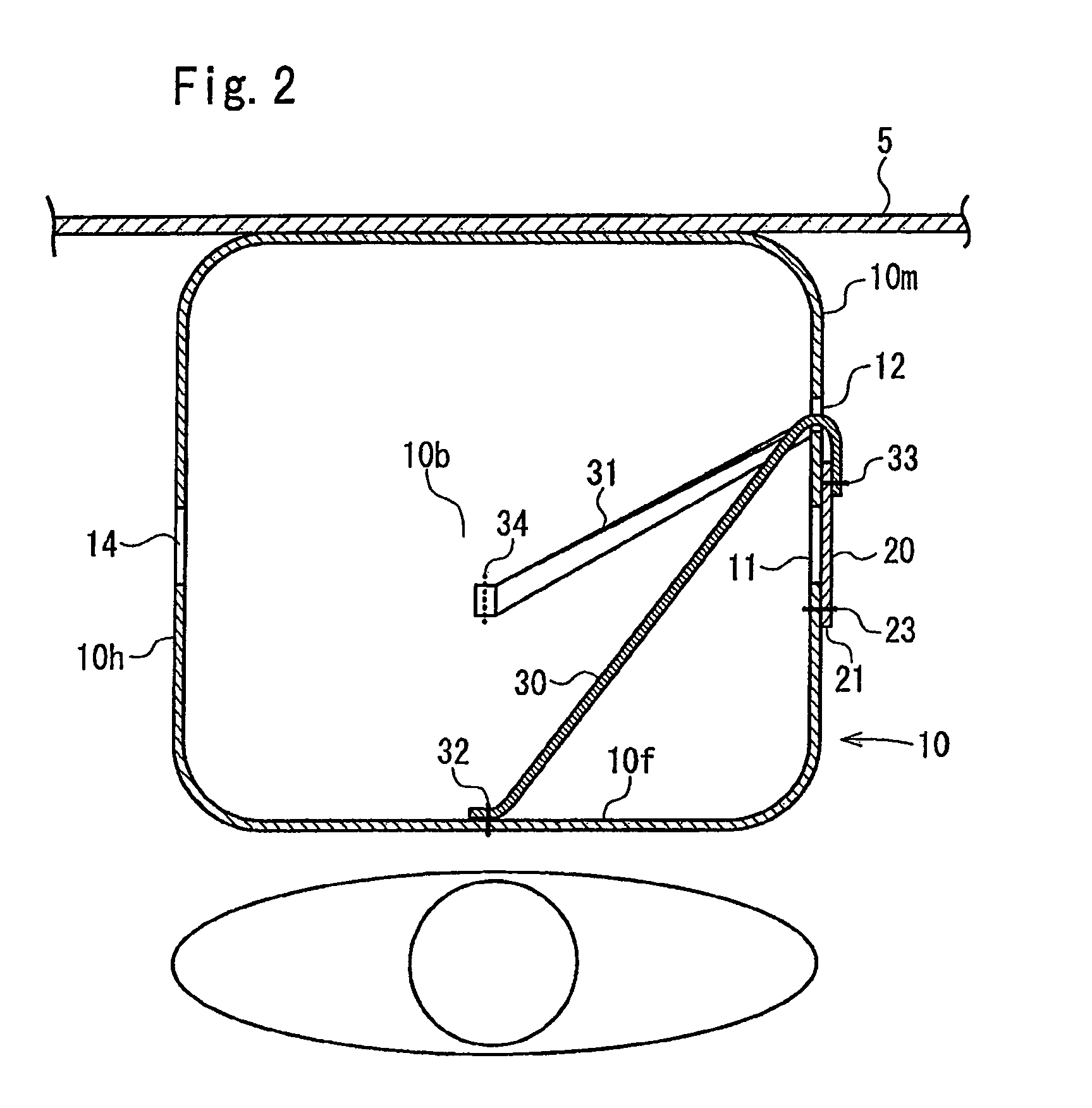
[0073]FIG. 1 is a side view of an airbag according to an embodiment in an inflated state. FIG. 2 is a cross-sectional view taken along the line II-II of FIG. 1. FIG. 3 is a side view showing a state where an occupant is in contact with a near-occupant face of the inflated airbag. FIG. 4 is a cross-sectional view taken along the line IV-IV of FIG. 3. FIG. 5 is a side view showing a state where a child seat is in contact with a lower portion of the inflated airbag.

[0074]An airbag 10 of this embodiment is an airbag for a passenger seat of a vehicle.

[0075]The airbag 10, in a folded state, is housed in a container 1 and is inflated by an inflator, i.e., a gas generator 2. The container 1 is provided in an instrument panel 3. The top of the container 1 is covered with a lid 4. A reference numeral 5 denotes a windshield.

[0076]In this embodiment, the airbag 10 in the inflated state has on one sid...


PUM


Abstract

An airbag and an airbag device are provided in which an openable-closable vent hole opens or significantly opens even if an object, such as a child seat, comes into contact with a lower portion of the airbag in an inflated state. A covering member (20) covers an openable-closable vent hole (11) from the outside of an airbag (10). An upper tether (30) routed through an upper constantly open vent hole (12) and in the inside of the airbag (10) connects the covering member and a near-passenger face (10f) of the airbag (10). A lower tether (31) routed through a lower constantly open vent hole (13) and in the inside of the airbag (10) connects the covering member and a lower portion (10b) of the airbag (10). When a passenger comes into contact with the near-passenger face (10f) of the airbag (10), the upper tether (30) loosens and the covering member (20) is turned up, whereby the openable-closable vent hole (11) opens. When a child seat (6) comes into contact with the lower portion (10b) of the airbag (10), the lower tether (31) loosens and the covering member (20) is turned up, whereby the openable-closable vent hole (11) opens.

Description

TECHNICAL FIELD[0001]The present invention relates to an airbag including a vent hole through which gas is discharged from the inside to the outside of the airbag, whereby shock is absorbed, and a covering member that covers the vent hole. The present invention also relates to an airbag device including the foregoing airbag.BACKGROUND ART[0002]It is widely known that an airbag is provided with a vent hole, through which gas inside the airbag is discharged when a vehicle occupant or the like bumps into the airbag in an inflated state, whereby the vehicle occupant or the like is softly received by the airbag.[0003]Japanese Unexamined Patent Application Publication No. 6-127330 discloses an airbag in which a vent hole is closed before an occupant comes into contact with a near-occupant face of the airbag in an inflated state, but the vent hole opens when the occupant comes into contact with the near-occupant face of the inflated airbag and causes the near-occupant face to retract.[0004...

Claims


Application Information

Patent Timeline
Patent Type & Authority Patents(United States)
IPC IPC(8): B60R21/16
CPCB60R21/2338B60R21/239B60R2021/23382
Inventor ABE, KAZUHIROKUMAGAI, MASAYOSHI
Owner TAKATA CORPORATION
Why Eureka
Try Eureka