

Transfer switch system with neutral current management
a transfer switch and neutral current technology, applied in the field of three-pole transfer switch system, can solve problems such as unwanted ground fault interrupter trips
- Summary
- Abstract
- Description
- Claims
- Application Information
AI Technical Summary
Benefits of technology
Problems solved by technology
Method used
Image


Examples
Embodiment Construction
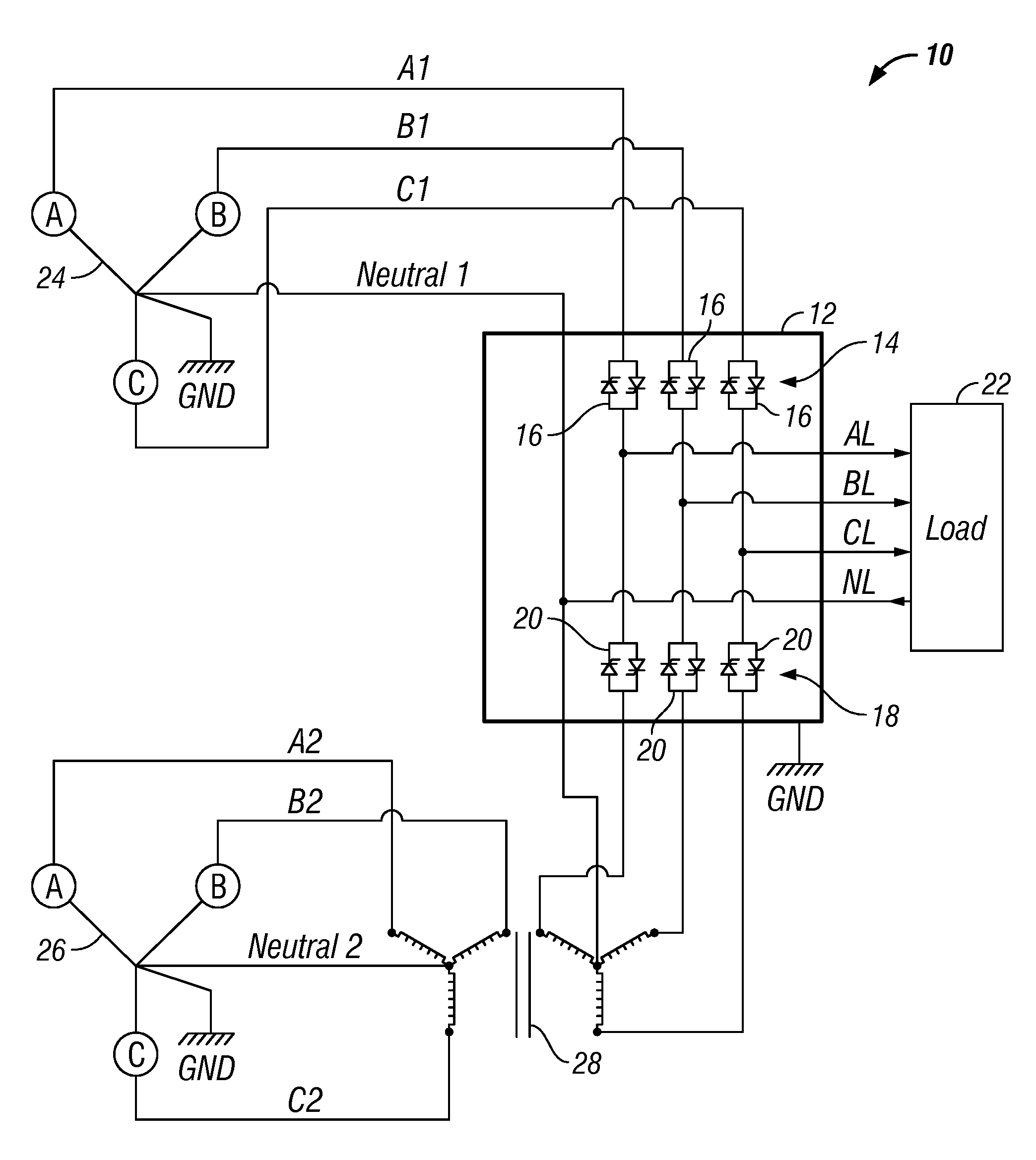
[0012]In general, the present invention comprises a electrical power transfer system configured to transfer a load between a first and second electrical power source without providing multiple neutral current paths between the power sources. For example, an automatic or manual transfer switch system according to the present invention may comprise an output connected to a load, a first switch for selectively connecting and / or disconnecting the load to the first power source, a second switch for selectively connecting and / or disconnecting the load to the second power source, wherein the neutral line of the second power source is isolated from the neutral line of the first power source and / or the neutral line of the load. One preferred embodiment comprises a transformer that has its input connected to the second power source and its output connected to the input of the second switch so that the neutral current line of the second power source is isolated from the load and / or the first p...
PUM
 Abstract
Description
Claims
Application Information