
Imaging apparatus capable of reducing deterioration of an image even when the gain increased

a technology of image deterioration and image, applied in the field of image deterioration, can solve the problems of image quality deterioration, excessive noise reduction, and image quality deterioration after compression coding, and achieve the effect of reducing image deterioration

Inactive Publication Date: 2011-04-26
CANON KK
View PDF10 Cites 21 Cited by
  • Summary
  • Abstract
  • Description
  • Claims
  • Application Information

AI Technical Summary

Benefits of technology

[0010]The present invention is directed to an imaging apparatus capable of reducing deterioration of an image even when the gain is increased.

Problems solved by technology

However, when the gain-increased image signal is compressed with MPEG-2, image quality may be deteriorated by a random noise component.
As a result of this, the number of bits which should be allotted to original image information decreases, and thus, image quality after the compression coding is largely deteriorated.
Since a video camera capable of outputting an image signal from a camera unit to an external includes noise reduction units both in the camera unit and an image compression unit, an excessive amount of noise reduction may be applied at the time of recording an image signal.
As a result, a high-frequency component of the image signal may be lost and image quality may be deteriorated.
This problem is noticeable when a photographer sets a noise reduction level in the camera unit to high and increases the gain of an amplifier.
Thus, when a camera image signal is directly output to an external with the gain increased, a noise of the camera image signal cannot be adjusted.

Method used


Image

  • Imaging apparatus capable of reducing deterioration of an image even when the gain increased
  • Imaging apparatus capable of reducing deterioration of an image even when the gain increased
  • Imaging apparatus capable of reducing deterioration of an image even when the gain increased

Examples


first exemplary embodiment

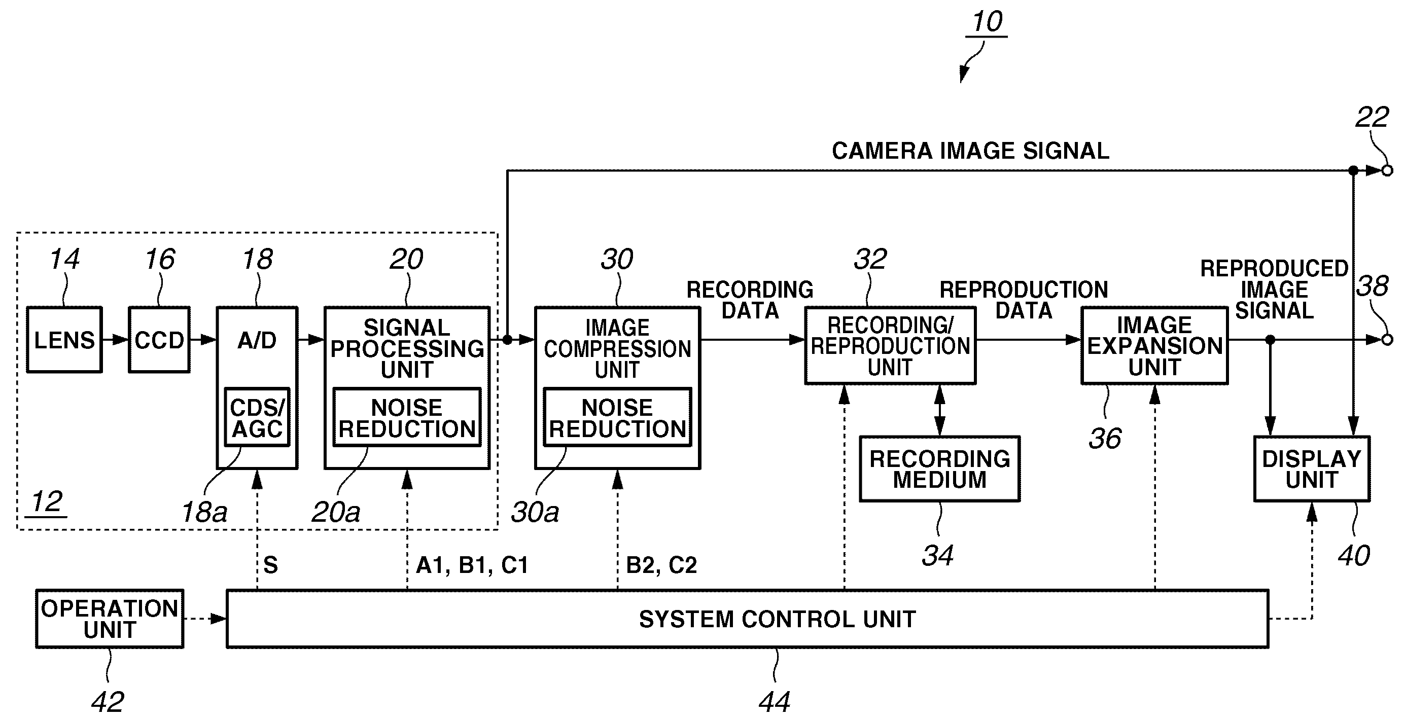
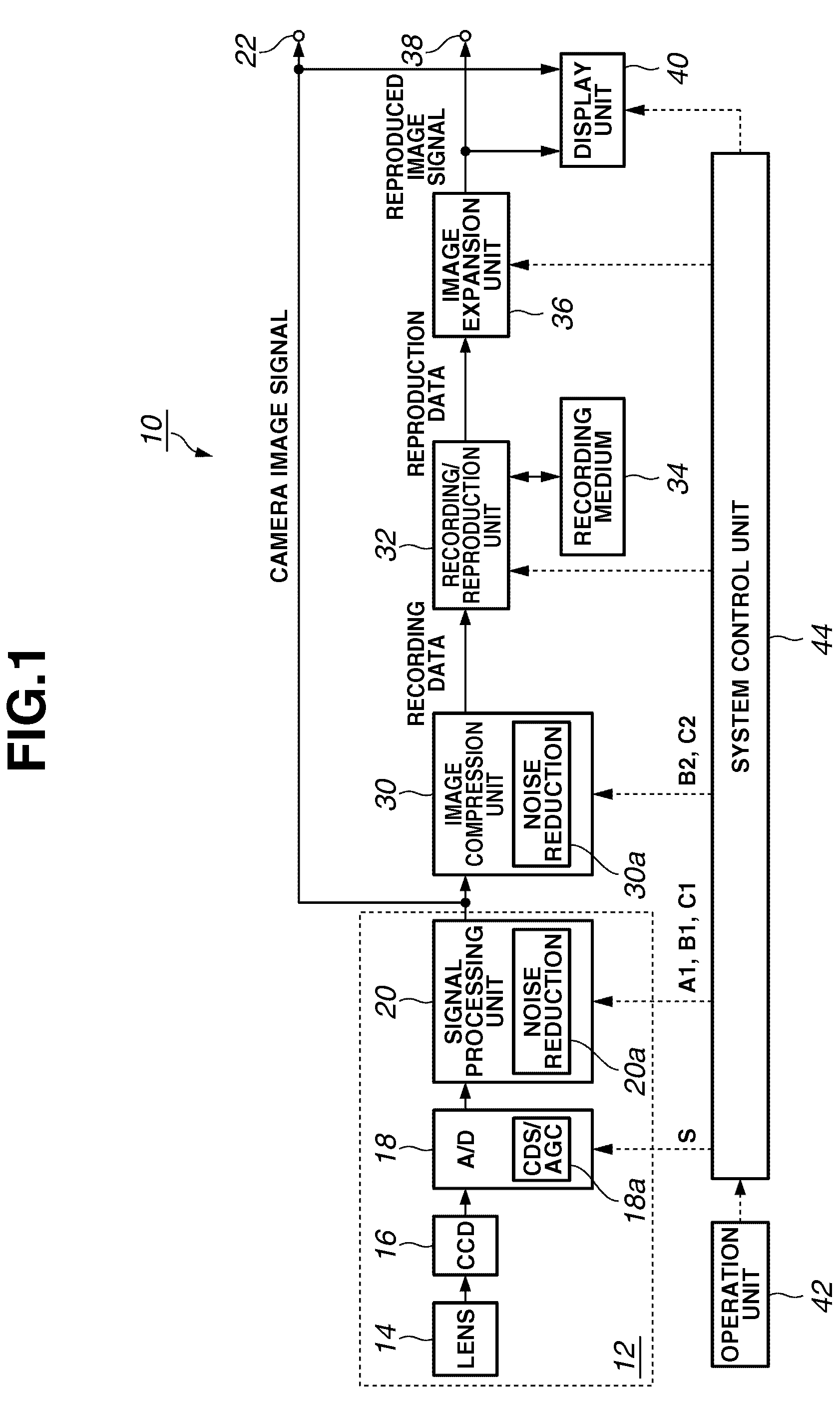
[0027]A first exemplary embodiment of the present invention will now herein be described. FIG. 1 is a block diagram showing an exemplary configuration of a camcorder 10 according to the first exemplary embodiment of the present invention. In FIG. 1, continuous lines indicate the flow of an image signal and dashed lines indicate the flow of a control signal.

[0028]A camcorder 10 is a digital video camera but may be a digital still camera or the like. The camcorder 10 includes an imaging unit 12, a camera image signal output terminal 22, an image compression unit 30, a recording / reproduction unit 32, a recording medium 34, an image expansion unit 36, a reproduced image signal output terminal 38, a display unit 40, an operation unit 42, and a system control unit 44.

[0029]The imaging unit 12 includes a lens system 14, a charge-coupled device (CCD) image sensor 16, an analog-to-digital conversion unit (A / D) 18, and a signal processing unit 20.

[0030]The lens system 14 includes a lens, a zo...


PUM


Abstract

An imaging apparatus includes an imaging unit configured to image an object, a gain adjustment unit configured to adjust a gain for an image signal output from the imaging unit, a signal processing unit configured to process the image signal, the signal processing unit including a first noise reduction unit to reduce a particular noise included in the image signal, an image compression unit configured to compress an image signal output from the signal processing unit, the image compression unit including a second noise reduction unit to reduce the particular noise included in the image signal output from the signal processing unit, and a control unit configured to set one of the first and second noise reduction units into an operative state and another unit into an inoperative state according to a gain adjustment by the gain adjustment unit.

Description

BACKGROUND OF THE INVENTION[0001]1. Field of the Invention[0002]The present invention relates to an imaging apparatus, and more particularly, to an imaging apparatus including a noise reducing function.[0003]2. Description of the Related Art[0004]In recent years, a technique for processing a digital signal has been developed, and thus a large amount of digital information, e.g., a moving image, a still image, sound, or the like, can be easily compressively coded so as to be recorded on a small recording medium or transmitted to a communication medium. More particularly, in the field of compression coding of an image, a standard technique for moving image coding, e.g., MPEG-2 (Moving Picture Experts Group phase 2), has become widely used, and digital video cameras using MPEG-2 has come into practical use.[0005]An imaging function of a digital video camera includes a function referred to as a gain increase. A photographer can perform high-sensitive shooting by intentionally increasing...

Claims


Application Information

Patent Timeline
Patent Type & Authority Patents(United States)
IPC IPC(8): H04N5/217H04N5/208H04N5/232
CPCH04N5/217H04N5/772H04N5/775H04N9/8042H04N5/85H04N5/907H04N5/781H04N23/81
Inventor TAKEI, HIROFUMI
Owner CANON KK
Learn More