Subject information acquiring device and subject information acquiring method
a subject information and acquisition device technology, applied in the field of subject information acquisition devices and subject information acquisition methods, can solve the problems of image to be obtained deterioration, band limitation, limited frequency of acoustic waves to be detected, etc., and achieve the effect of reducing image deterioration
- Summary
- Abstract
- Description
- Claims
- Application Information
AI Technical Summary
Benefits of technology
Problems solved by technology
Method used
Image
Examples
example 1
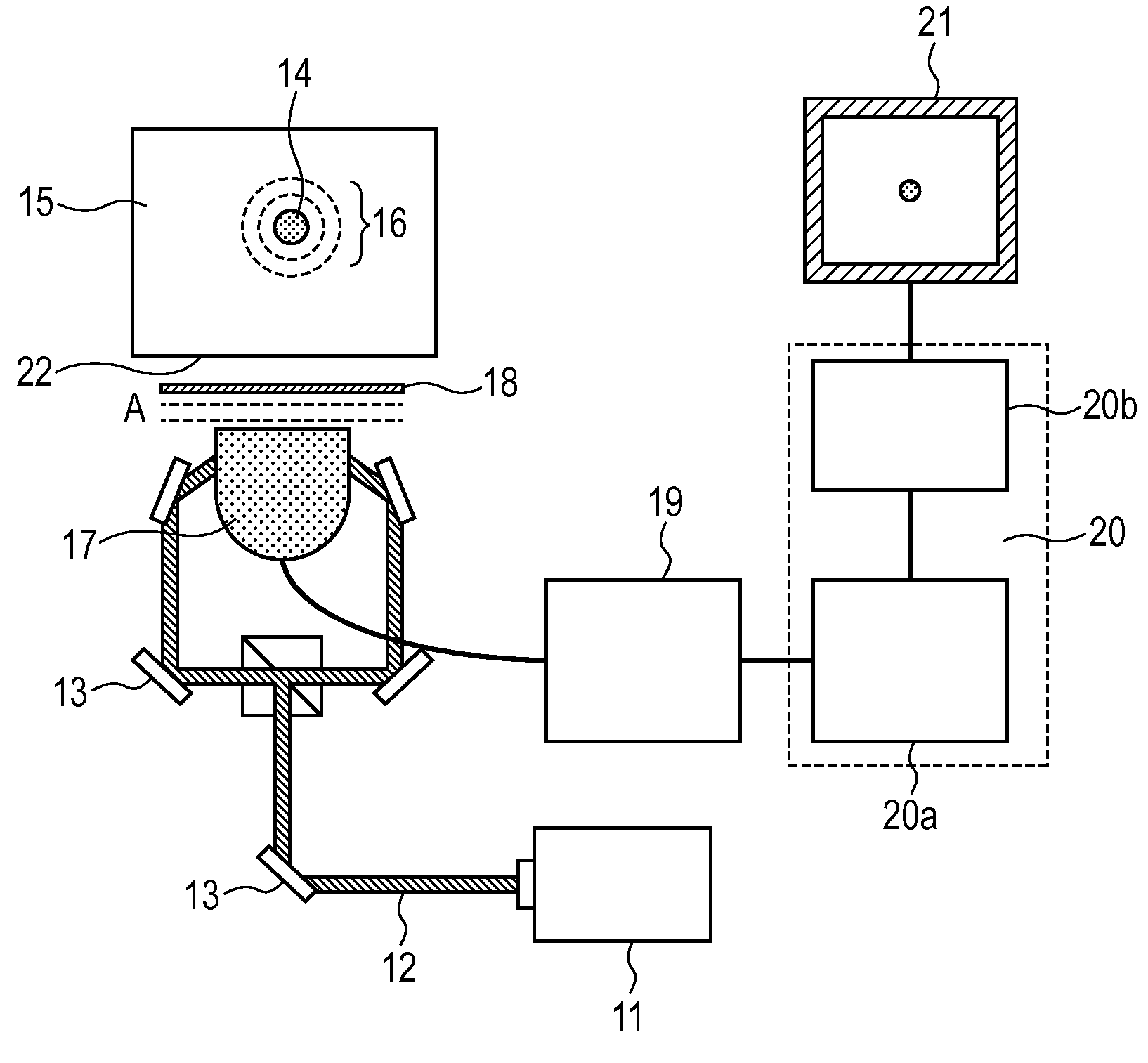
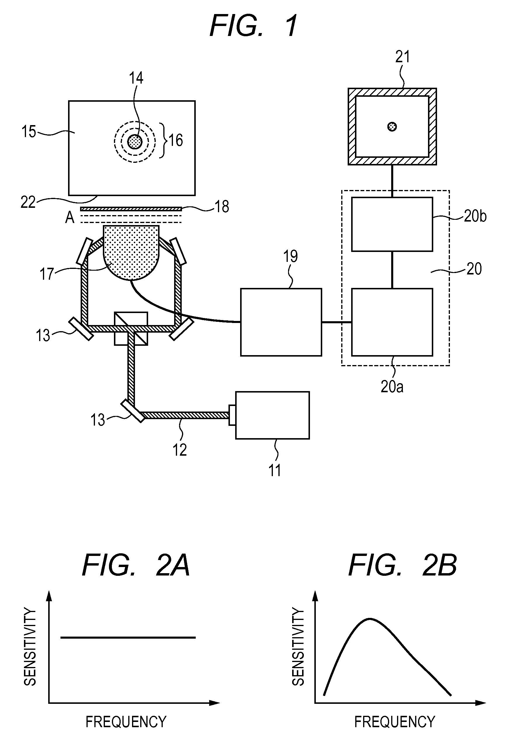
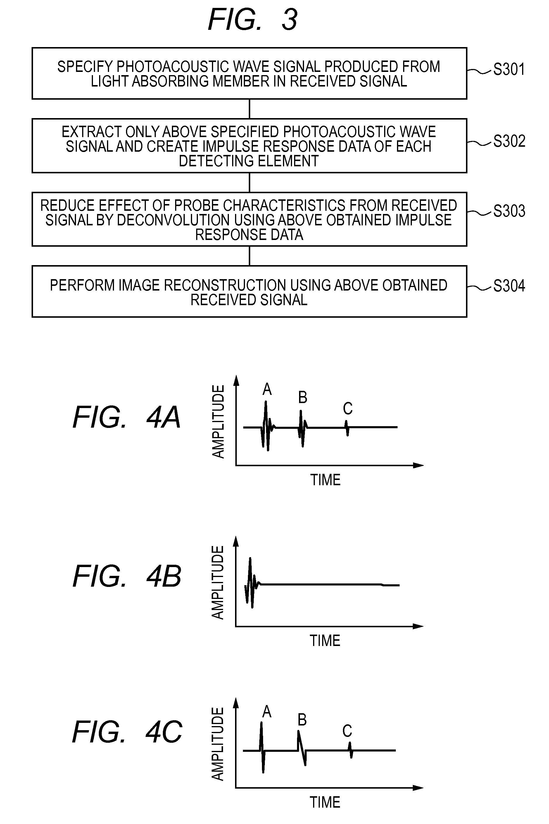
[0049]With reference to the schematic views of the device in FIGS. 1 and 5A, an example of a subject information acquiring device using a photoacoustic tomography to which the present embodiment is applied will be described. In the present embodiment, a Q switch YAG laser which produces pulsed light of about 10 nanoseconds at the wavelength of 1064 nm was used for the light source 11. The energy of pulsed light emitted from the pulse laser light 12 was 0.6 J, and the optical system 13 was set such that this pulsed light was expanded to have the diameter of about 1 cm, using the optical system 13 such as a mirror and beam expander, and then the pulsed light was separated into two by a beam splitter to radiate on the subject directly below the probe using the mirror and prism. For the subject 15, a rectangular phantom as illustrated in FIG. 5A which simulates the biological body was used. The phantom was utilized by solidifying 1% of an intralipid by an agar. The size of the phantom w...
example 2
[0054]An example of a subject information acquiring device using a photoacoustic tomography to which the present embodiment is applied will be described. In the present embodiment, the same phantom and measuring system as in Example 1 were used. Meanwhile, to simulate a change of probe characteristics, sensitivities of amplifiers at a later stage in 80 elements corresponding to about one fourth of elements of 345 channels of the two-dimensional array detector were reduced to 50%, thereby change of sensitivity characteristics were simulated. Next, similar to Example 1, light was radiated on the phantom, and the resulting digital data was transferred to a workstation (WS) which is the signal processing unit 20 and the data was stored in the WS. Then, similar to Example 1, using the photoacoustic wave signal resulting from the optical absorber, an impulse response of each receiving element was calculated, and the detection signal was corrected using the impulse response. Further, using...
example 3
[0056]An example of a subject information acquiring device using a photoacoustic tomography to which the present embodiment is applied will be described. In the present embodiment, the same phantom and measuring system as in Example 1 were used. An impulse response of a probe used in Example 1 had been measured before the probe was mounted in the measuring system, and the impulse response was stored in the WS. Next, a probe made on another day (a probe different from one used in Example 1) was mounted on the measuring system to change probe characteristics. Similar to Example 1, light was radiated on the phantom, and the resulting digital data was transferred to a workstation (WS) which is the signal processing unit 20 and the data was stored in the WS. Then, similar to Example 1, using a detection signal corrected using the photoacoustic wave signal resulting from the light absorbing member, an image was obtained. As a result, the substantially same data as in FIG. 6A without deter...
PUM
 Abstract
Description
Claims
Application Information
 - R&D
- Intellectual Property
- Life Sciences
- Materials
- Tech Scout
- Unparalleled Data Quality
- Higher Quality Content
- 60% Fewer Hallucinations
Browse by: Latest US Patents, China's latest patents, Technical Efficacy Thesaurus, Application Domain, Technology Topic, Popular Technical Reports.
© 2025 PatSnap. All rights reserved.Legal|Privacy policy|Modern Slavery Act Transparency Statement|Sitemap|About US| Contact US: help@patsnap.com


