Image pickup apparatus and image conversion method
a pickup apparatus and image technology, applied in the field of image pickup apparatus and image conversion method, can solve the problems of image quality degradation, image quality degradation, image quality degradation, etc., and achieve the effect of reducing image quality degradation
- Summary
- Abstract
- Description
- Claims
- Application Information
AI Technical Summary
Benefits of technology
Problems solved by technology
Method used
Image
Examples
first embodiment
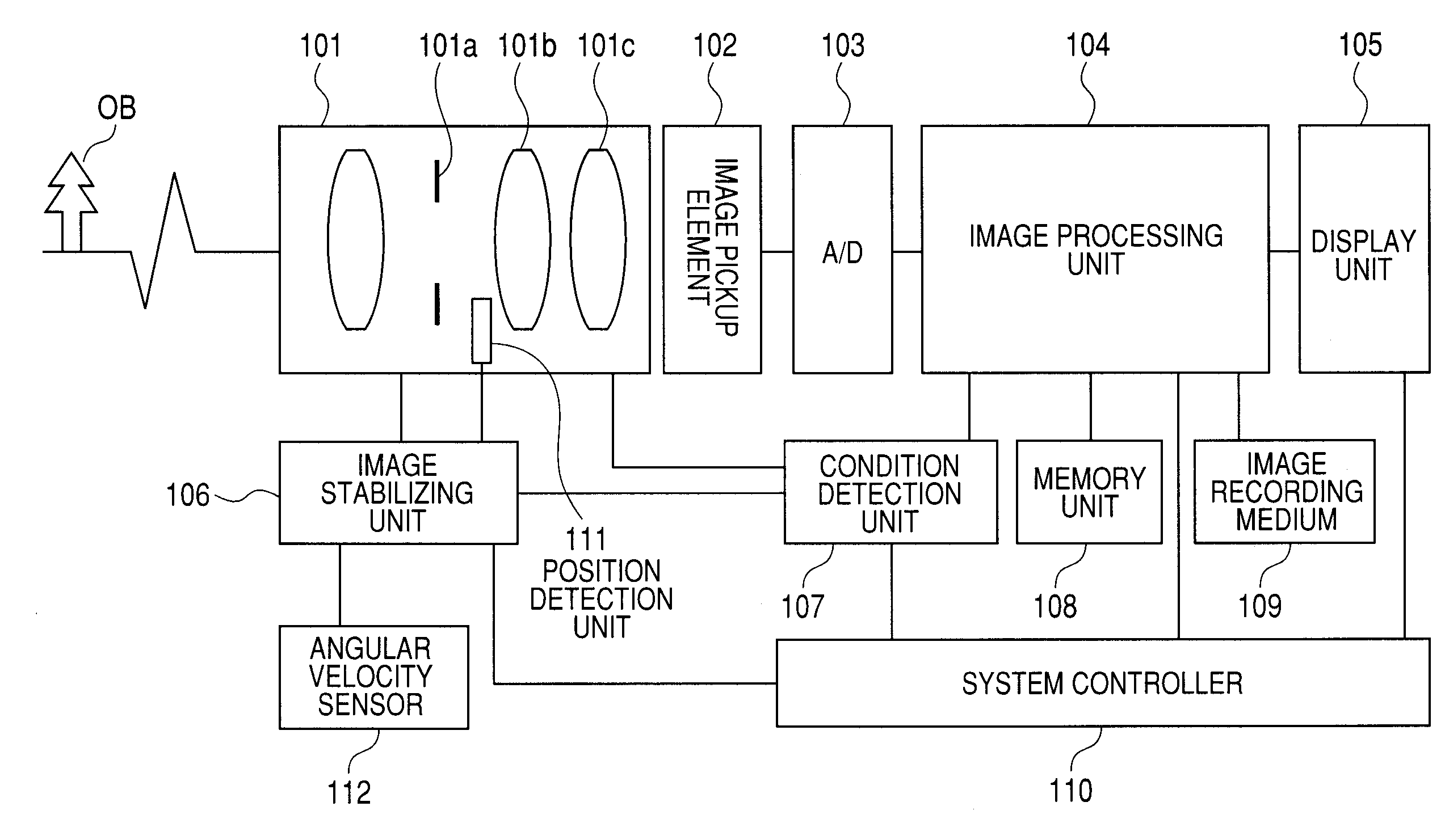
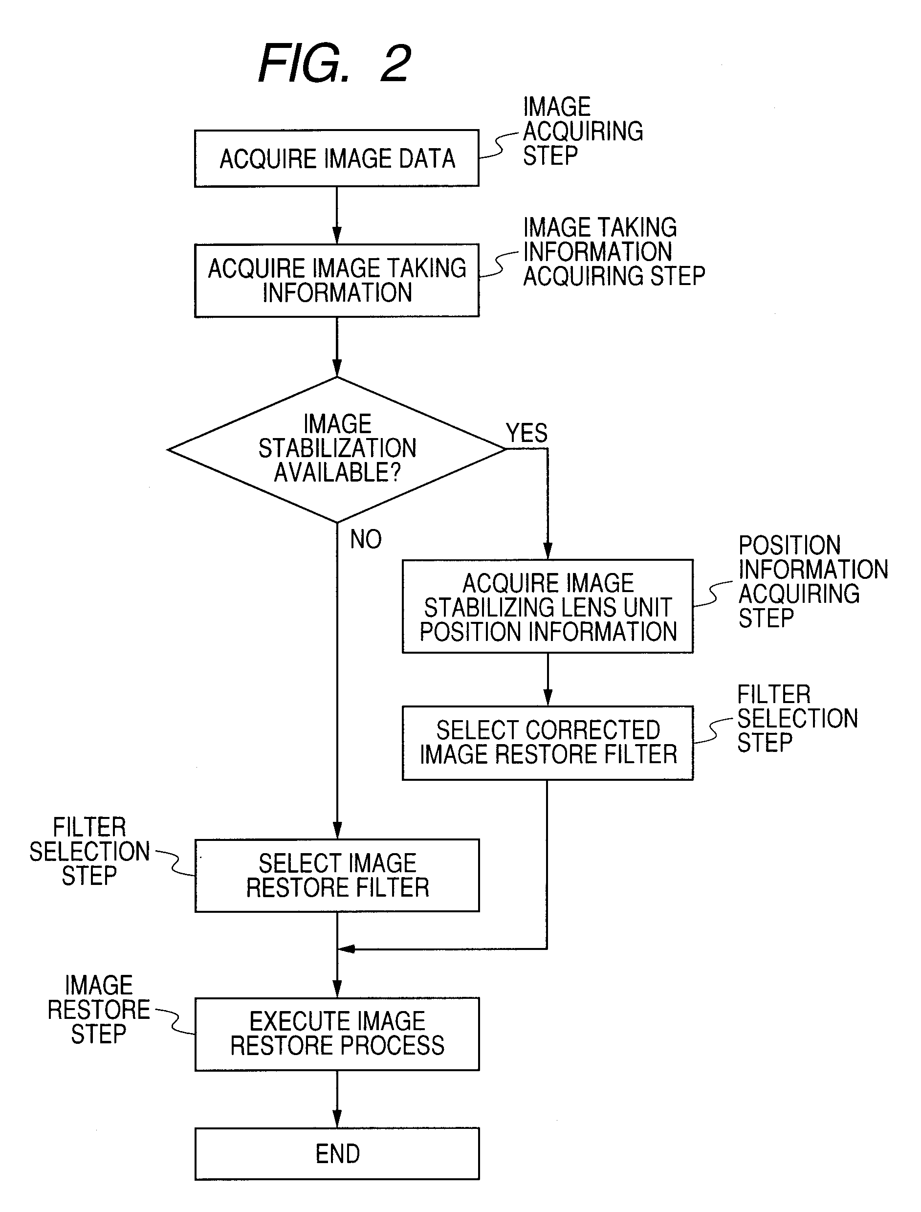
[0042]In the first embodiment, a mean position of the image stabilizing lens unit 101b is obtained during the exposure time at the time of the image taking. If the position of the image stabilizing lens unit 101b is caused to change during the exposure time as illustrated in FIG. 7, the image restore filter based on optical performance corresponding to the mean position of the image stabilizing lens unit 101b is selected for the taken image, and the image restore process is executed by the image processing unit 104. By performing such an image restore process, the degradation of the image due to the decentration aberration of the image pickup optical system 101 may be corrected. Therefore, satisfactory image quality may be obtained with the image shake corrected. In this embodiment, information to be prepared for the multidimensional matrix is the image restore filter.
[0043]According to this embodiment, by performing the image process on the image stabilizing lens unit 101b within t...
second embodiment
[0044]In a second embodiment, a new point spread function (PSF) is obtained by calculating a mean value of the point spread functions (PSFs) corresponding to respective positions of the image stabilizing lens unit 101b within the exposure time. The image restore filter is created based on the new point spread function (PSF), and the image restore process is executed on the taken image. In this embodiment, the information to be prepared for the multidimensional matrix is the point spread function (PSF). As described above, in this embodiment, the image restore filter for the image stabilization is created based on a point spread function obtained by calculating the mean value of the point spread functions (PSFs) corresponding to the respective positions of the image stabilizing lens unit 101b within the optical image stabilization system. FIG. 3 is a flowchart regarding such an image conversion method according to the second embodiment. The image conversion method according to this e...
third embodiment
[0045]FIG. 8 is a schematic diagram of main components according to a third embodiment of the present invention. FIG. 8 illustrates the same configuration as FIG. 1 except that the position detection unit 111 detects a position of the image pickup element 102 in an optical axis direction. The third embodiment is different from the first and second embodiments in that the image pickup element image stabilization system corrects the image shake by causing the image pickup element 102 to move in such a direction as to have a component in the direction perpendicular to the optical axis. By performing the image process to which the image restore filter as in the first and second embodiments is applied, the degradation of the image caused when the image shake is corrected by moving the image pickup element may be reduced. According to each of the exemplary embodiments of the present invention, the image pickup apparatus and the image conversion method which may reduce the degradation of t...
PUM
 Abstract
Description
Claims
Application Information
 - R&D
- Intellectual Property
- Life Sciences
- Materials
- Tech Scout
- Unparalleled Data Quality
- Higher Quality Content
- 60% Fewer Hallucinations
Browse by: Latest US Patents, China's latest patents, Technical Efficacy Thesaurus, Application Domain, Technology Topic, Popular Technical Reports.
© 2025 PatSnap. All rights reserved.Legal|Privacy policy|Modern Slavery Act Transparency Statement|Sitemap|About US| Contact US: help@patsnap.com


