Protection switching method based on change in link status in ethernet link aggregation sublayer

a protection switching and sublayer technology, applied in data switching networks, frequency-division multiplexes, instruments, etc., can solve problems such as insufficient coping, failure to detect bandwidth reduction, and connections above physical layers

Inactive Publication Date: 2011-05-10
ELECTRONICS & TELECOMM RES INST
View PDF15 Cites 5 Cited by
  • Summary
  • Abstract
  • Description
  • Claims
  • Application Information

AI Technical Summary

Benefits of technology

[0018]The present invention provides an Ethernet protection switching method that enables adequate Ethernet protection switching to be performed based on a change in an Ethernet link status when a link aggregation sublayer is present in links constituting a lower part of an Ethernet connection.

Problems solved by technology

However, adequately coping with faults caused by damage in other physical layers is difficult when employing protection switching in the PMD layer, and supporting protection switching of data flows above a Media Access Control (MAC) layer in the event of connection with a multi-stage system is difficult when protection switching is employed in some physical layers.
In the case where a lower part of the physical layer is made of a single link or serially connected single-links, damage to the physical layer causes connections above the physical layer, i.e. exchange of the continuity check messages, to be interrupted.
However, when an aggregation of links connected in parallel is used in some sections, the use of continuity check messages alone may fail to detect reduction of bandwidth due to failure of some links in the group, disrupting Ethernet traffic.
In this case, reduced bandwidth leads to total failure of the Ethernet network.
However, this trouble is not detected between the MEG end points and protection switching is not performed.

Method used


Image

  • Protection switching method based on change in link status in ethernet link aggregation sublayer
  • Protection switching method based on change in link status in ethernet link aggregation sublayer
  • Protection switching method based on change in link status in ethernet link aggregation sublayer

Examples


Embodiment Construction

[0027]The invention is described more fully hereinafter with reference to the accompanying drawings, in which exemplary embodiments of the invention are shown. This invention may, however, be embodied in many different forms and should not be construed as limited to the exemplary embodiments set forth herein. Rather, these exemplary embodiments are provided so that this disclosure is thorough, and will fully convey the scope of the invention to those skilled in the art.

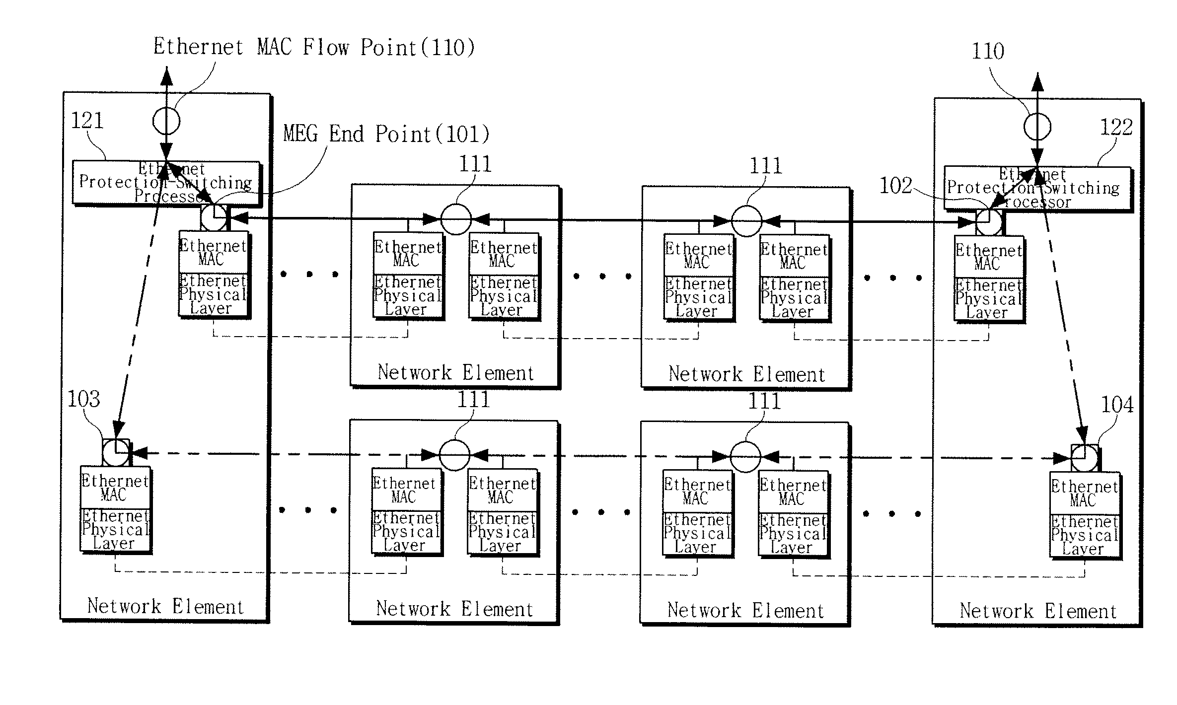
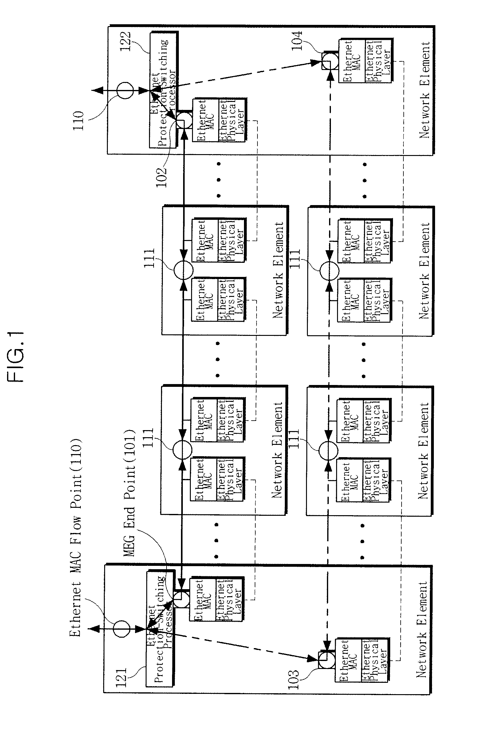
[0028]FIG. 1 is a diagram illustrating an example of Ethernet management and protection switching. In an Ethernet connection, each of Ethernet MAC flow points 110 and 111 present in individual Ethernet devices determines data flow, and MEG end points 101 and 102 are respectively set to starting and end points of the connection to manage the data flow.

[0029]For protection switching, working MEG end points 101 and 102 for a working connection and preliminary MEG end points 103 and 104 for a preliminary connection are pr...


PUM


Abstract

An Ethernet protection switching method based on a change in link status in a link aggregation sublayer is disclosed. If an Ethernet link aggregation sublayer is present on an Ethernet connection path, a link aggregation sublayer Management Entity Group (MEG) end point is assigned to the Ethernet link aggregation sublayer to generate a link aggregation message for Ethernet connection management and protection switching. When a change in link status is detected in the Ethernet link aggregation sublayer, the link-aggregation-sublayer MEG end point generates and sends the link aggregation message to an MEG end point performing Ethernet connection management and protection switching. Adequate Ethernet protection switching may be performed even in the presence of the link aggregation sublayer.

Description

CROSS REFERENCE TO RELATED APPLICATIONS[0001]This application claims priority from Korean Patent Application No. 10-2007-0129179, filed on Dec. 12, 2007, the disclosure of which is incorporated herein its entirety by reference.BACKGROUND OF THE INVENTION[0002]1. Field of the Invention[0003]The present invention relates to an Ethernet protection switching method, and more particularly to an Ethernet protection switching method based on a change in link status in an Ethernet link aggregation sublayer, wherein, when faults occur in an Ethernet link, the Ethernet link is protection-switched to an adequate link.[0004]This work was supported by the IT R&D program of Ministry of Information and Communication (MIC) / Institute for Information Technology Advancement (IITA) [2005-S-102-03. Carrier Class Ethernet Technology].[0005]2. Description of the Related Art[0006]Ethernet protection switching may be performed in various manners, such as protection switching in a physical layer via detectio...

Claims


Application Information

Patent Timeline
Patent Type & Authority Patents(United States)
IPC IPC(8): G01R31/08
CPCH04L69/323H04L43/0811H04L41/06H04L45/28
Inventor KIM, DAE-UBRYOO, JEONG-DONGJOO, BHEOM-SOONKIM, YOUNG-SUN
Owner ELECTRONICS & TELECOMM RES INST
Why Eureka
Try Eureka