Link aggregation split-brain detection and recovery

a split-brain detection and link technology, applied in the field of data networking, can solve the problems of increasing the latency of network data propagation through the network nodes, and the implementations known in the art are generally unable to distinguish between a node failure and a communication failure between the various nodes of a multi-chassis lag configuration

Active Publication Date: 2017-06-08
ARISTA NETWORKS
View PDF23 Cites 106 Cited by
  • Summary
  • Abstract
  • Description
  • Claims
  • Application Information

AI Technical Summary

Benefits of technology

[0006]One embodiment provides for a network system comprising a set of peers within a link aggregation group (LAG), the first set of peers including a first network element and a second network element and a status resolution server to connect to the set of peers within the link aggregation group, wherein one or more peers within the LAG is to query the status resolution server to determine an operational status of a peer in the set of peers in response to detection of an apparent failure of the peer the detection of the apparent failure of the peer can include detection of a loss of communication with the peer over a peer link including one or more network connections and the status resolution server can be configured to to receive a query from the second network element and determine an operational status of the first network element. The second network element can periodically query the status resolution server to determine the operational status of the first network element. The status resolution server can then determine the operational status of the first network element in response to detection of a loss of communication with the first network element. The status resolution server can determine the operational status of the first network element via a query to the first network element, via a heartbeat protocol, or via a query to a central database of the first network element.
[0007]One embodiment provides for a non-transitory machine readable medium storing instructions which, when executed by one or more control plane processors of a network element, cause the network element to perform operations comprising configuring the network element as a first peer of a link aggregation group (LAG), the first peer coupled to a second peer via a peer link including one or more network connections; in response to a loss of communication over the peer link, assuming operations of the second peer; querying a status resolution server connected to the network element via a network to determine an operational status of the second peer; and resuming operation as the first peer in response to receiving an indication that the second peer is operational.
[0008]One embodiment provides for a network element comprising a control plane including one or more processors and memory, wherein the control plane is to configure the network element as a first peer of a link aggregation group (LAG) and a data plane coupled to the control plane, the data plane including a network interface having one or more peer ports and one or more non-peer ports, the one or more peer ports to couple to a second peer of the MLAG and the one or more non-peer ports to couple to an external device, wherein in response to a loss of communication with the second peer via the one or more peer ports, the control plane is to cause the network element to assume operational duties of the second peer and query a status resolution server for an operational status of the second peer.
[0009]One embodiment provides for a network system comprising a link aggregation group (LAG) including multiple network elements, the multiple network elements interconnected via a peer link including one or more network connections; a status resolution server to monitor operational status of network elements of the MLAG and a link state of the peer link; and wherein the status resolution server is further to detect occurrence of a split brain scenario caused by a failure of the peer link and automatically re-configure one or more network elements of the LAG to resolve the split brain scenario.
[0010]One embodiment provides for a method of managing operations of one or more network elements of a link aggregation group (LAG), the method comprising monitoring operational status of one or more network elements of the LAG; monitoring a link state of a peer link, the peer link including one or more network connections between the network elements of the LAG; detecting occurrence of a split brain scenario caused by a failure of the peer link; and automatically re-configuring one or more network elements of the LAG to resolve the split brain scenario.

Problems solved by technology

When the amount of network data that is to be transmitted by one of the ports on a network element, or the overall data transmitted by a network element, is greater than the port or network element can handle within a given period, network congestion can occur, resulting in increased latency for network data propagation through the nodes on the network.
However, implementations known in the art are generally unable to distinguish between a node failure and a communication failure between the various nodes of a multi-chassis LAG configuration.

Method used


Image

  • Link aggregation split-brain detection and recovery
  • Link aggregation split-brain detection and recovery
  • Link aggregation split-brain detection and recovery

Examples


Embodiment Construction

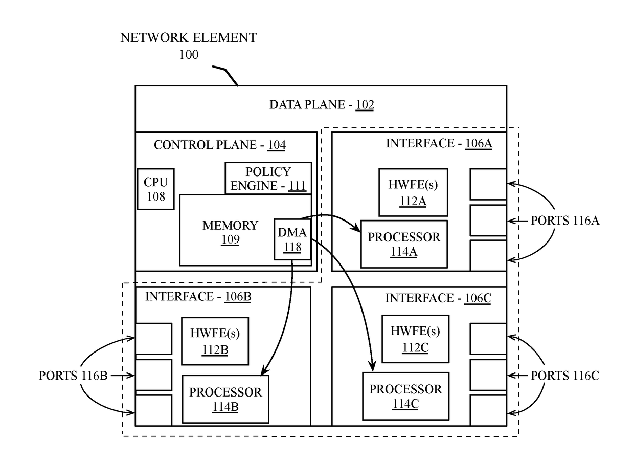
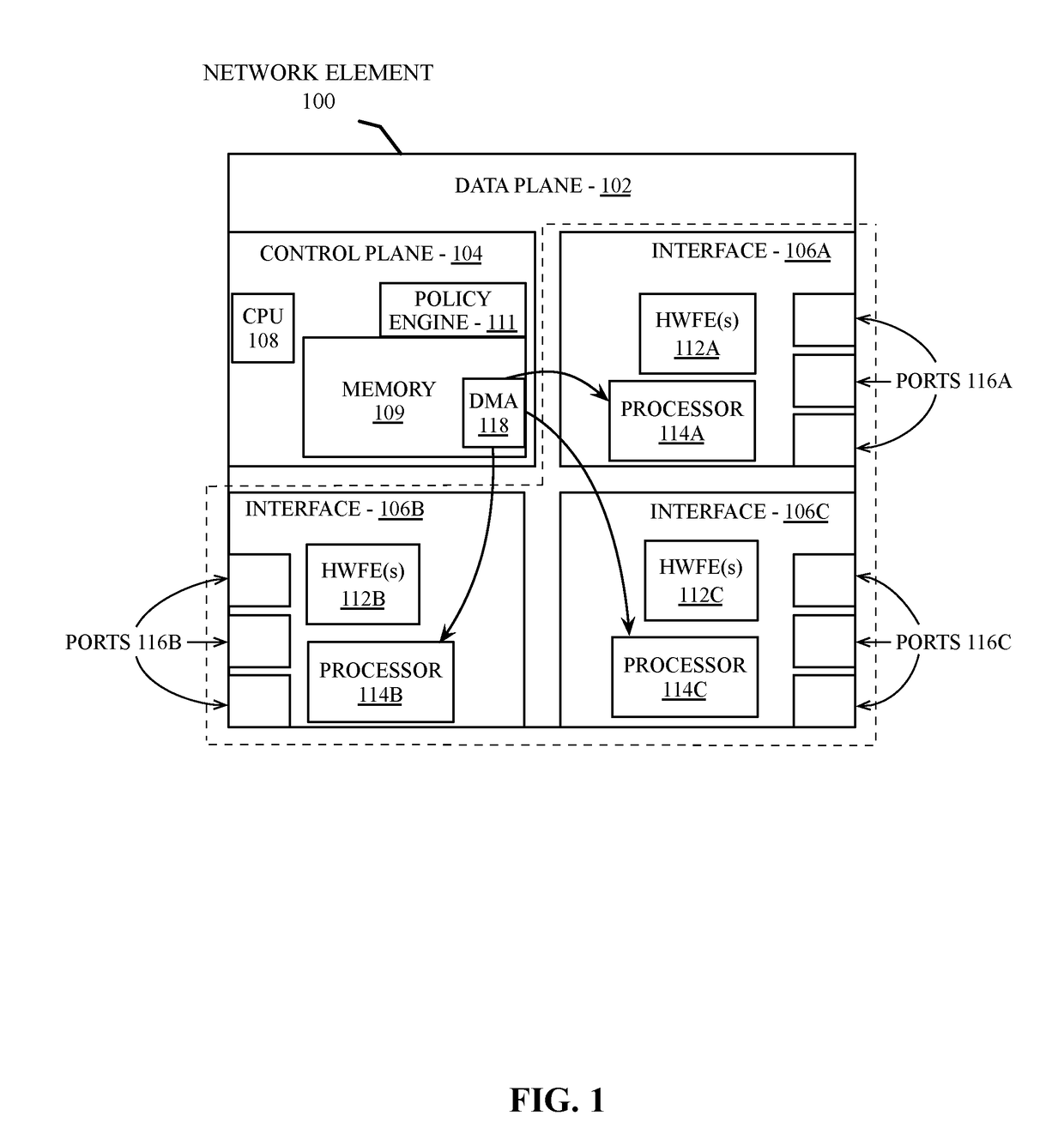
[0023]Embodiments described herein provide a multi-chassis LAG (MLAG) mechanism that enables an active-active link aggregation control protocol (LACP) connection to two or more network elements. In one embodiment, the MLAG mechanism includes logic to distinguish between a link failure and a node failure within the MLAG to detect and recover from a multi-chassis split-brain scenario. A split-brain scenario occurs when communication is lost between the network element nodes within a multi-chassis LAG and each node continues to operate as though the other node(s) in the LAG have failed. In some scenarios this can lead to network congestion or network errors due to forwarding loops.

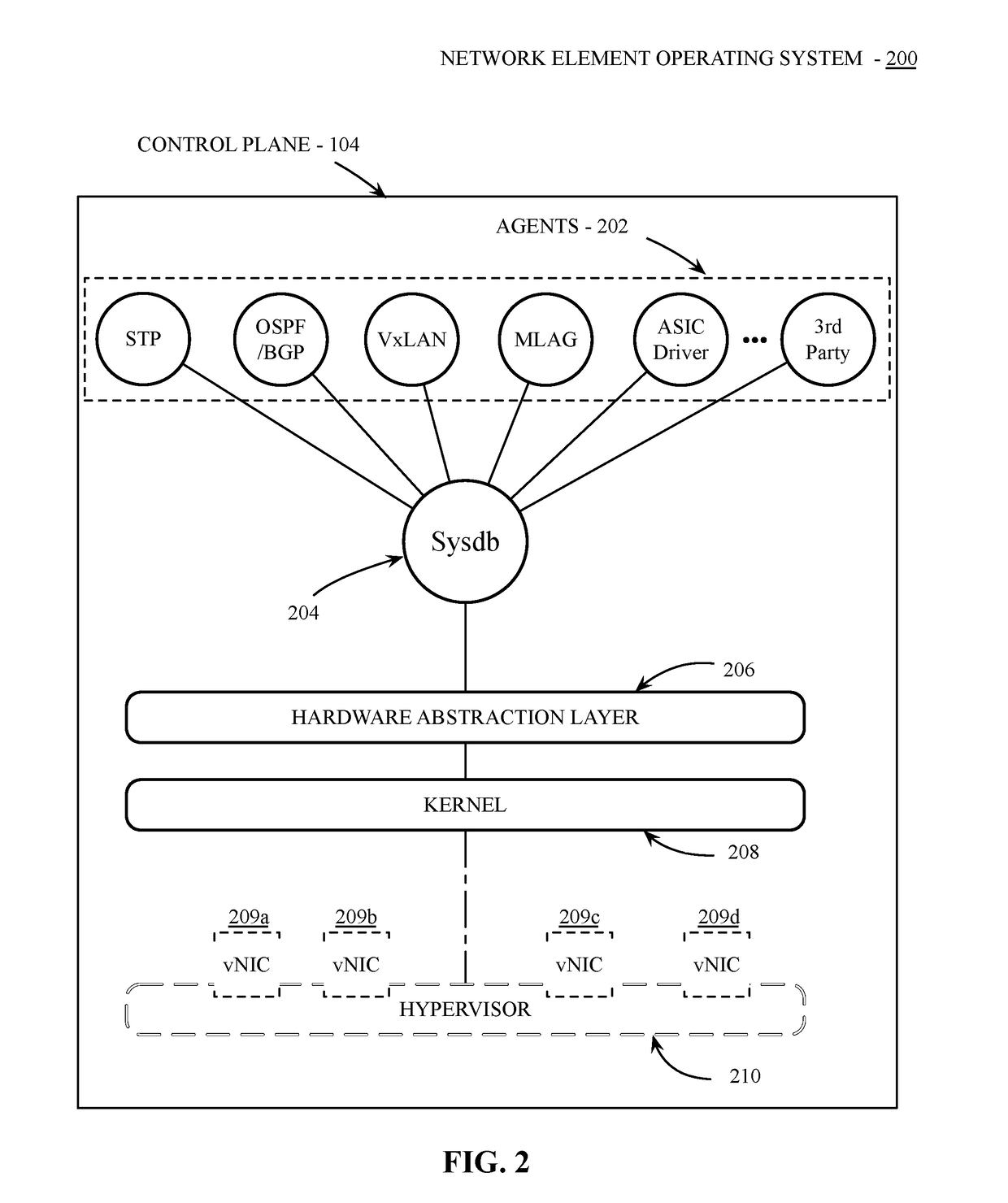
[0024]To detect and recover from a split-brain scenario, network elements in an MLAG configuration can determine peer status via a network management system in communication with network elements within the network system. In one embodiment, an in-band network API is provided by the network management system ...


PUM


Abstract

Various embodiments are described herein that provide a network system comprising a set of peers within a link aggregation group (LAG), the first set of peers including a first network element and a second network element and a status resolution server to connect to the set of peers within the link aggregation group, wherein one or more peers within the LAG is to query the status resolution server to determine an operational status of a peer in the set of peers in response to detection of an apparent failure of the peer.

Description

RELATED APPLICATIONS[0001]Applicant claims the benefit of priority of prior, co-pending provisional application Ser. No. 62 / 263,480, filed Dec. 4, 2015, the entirety of which is incorporated by reference.FIELD OF INVENTION[0002]This invention relates generally to data networking and more particularly to the management of multi-chassis link aggregation in networked devices.BACKGROUND OF THE DESCRIPTION[0003]A network element (such as a router or switch) transmits and receives network data using one or more ports of that network element. Each port on the network element has a physical link speed that limits the rate at which network data can be transmitted from that port. The network element uses one or more queues to store the network data that is to be transmitted from one of the ports of the network element. The maximum data that a queue stores is determined by the available buffer memory and a buffer configuration for the queue. When the amount of network data that is to be transm...

Claims


Application Information

Patent Timeline
Patent Type & Authority Applications(United States)
IPC IPC(8): H04L12/24H04L12/26H04L12/891H04L12/803H04L12/703H04L12/709H04L45/28H04L45/243H04L47/41
CPCH04L41/0645H04L45/28H04L45/245H04L41/0672H04L47/125H04L43/10H04L43/0817H04L47/41H04L41/0668Y02D30/50H04L41/0661
Inventor SADANA, ANSHULPARTHASARATHY, PRASANNASWEENEY, ADAM JAMES
Owner ARISTA NETWORKS
Why Eureka
Try Eureka