System and method for implementing logical switches in a network system

a network system and logical switch technology, applied in the field of computer network systems, can solve the problems of inability to meet the demands of today's enterprises, the inherent limitation of the pci system discussed above, and the inability to change the pci system architecture at the same pa

Inactive Publication Date: 2007-03-27
TAHOE RES LTD
View PDF7 Cites 280 Cited by
  • Summary
  • Abstract
  • Description
  • Claims
  • Application Information

AI Technical Summary

Benefits of technology

[0023]The present invention is also directed to a shared I/O subsystem for providing network protocol management for a plurality of computer systems. The shared I/O subsystem includes a plurality of I/O interfaces where each of the I/O interfaces operatively couples one of the computer systems to the shared I/O subsystem. The shared I/O subsystem also includes an I/O management link that operatively interconnects the I/O interfaces, and a link layer switch that communicatively couples to each of the I/O interfaces. The link layer switch receives a data packet from one of the I/O interfaces and directs the data packet to one or more of the other ones of the I/O interfaces. The I/O interfaces may form a local area network within the shared I/O subsystem.
[0024]The present invention is also directed to a shared I/O subsystem that includes a plurality of I/O interfaces for coupling a plurality of computer systems where each of I/O interfaces communicatively couples one of the computer systems to the shared I/O subsystem. The shared I/O subsystem receives, at a first one of the I/O interfaces, a data packet from one of the computer systems coupled to the first one of the I

Problems solved by technology

However, while virtually all aspects of the computer technology, such as a processor or memory, advanced dramatically, especially over the past decade, the PCI system architecture has not changed at the same pace.
The current PCI system has become considerably outdated when compared to other components of today's technology.
It should be apparent that the inherent limitation of the PCI system discussed above may not be feasible for meeting the demands of today's enterprises.
While the current PCI system generally servers the computing needs for many individuals using microcomputers, it does not adequately accommodate the computing needs of today's enterprises.
A poor bandwidth, reliability, and scalability, for instance, are just a few exemplary areas where the current PCI system needs to be addressed.
Constant CPU interruptions decrease overall CPU performance, thereby decreasing much of the benefits of increased processor and memory speeds provided by today's technology.
For many enterprises that use a traditional network system, these issues become even more significant as the siz

Method used


Image

  • System and method for implementing logical switches in a network system
  • System and method for implementing logical switches in a network system
  • System and method for implementing logical switches in a network system

Examples


Embodiment Construction

[0043]Reference will now be made in detail to the preferred embodiments of the present invention, examples of which are illustrated in the accompanying drawings. Wherever possible, the same reference numbers will be used throughout the drawings to refer to the same or like parts and steps.

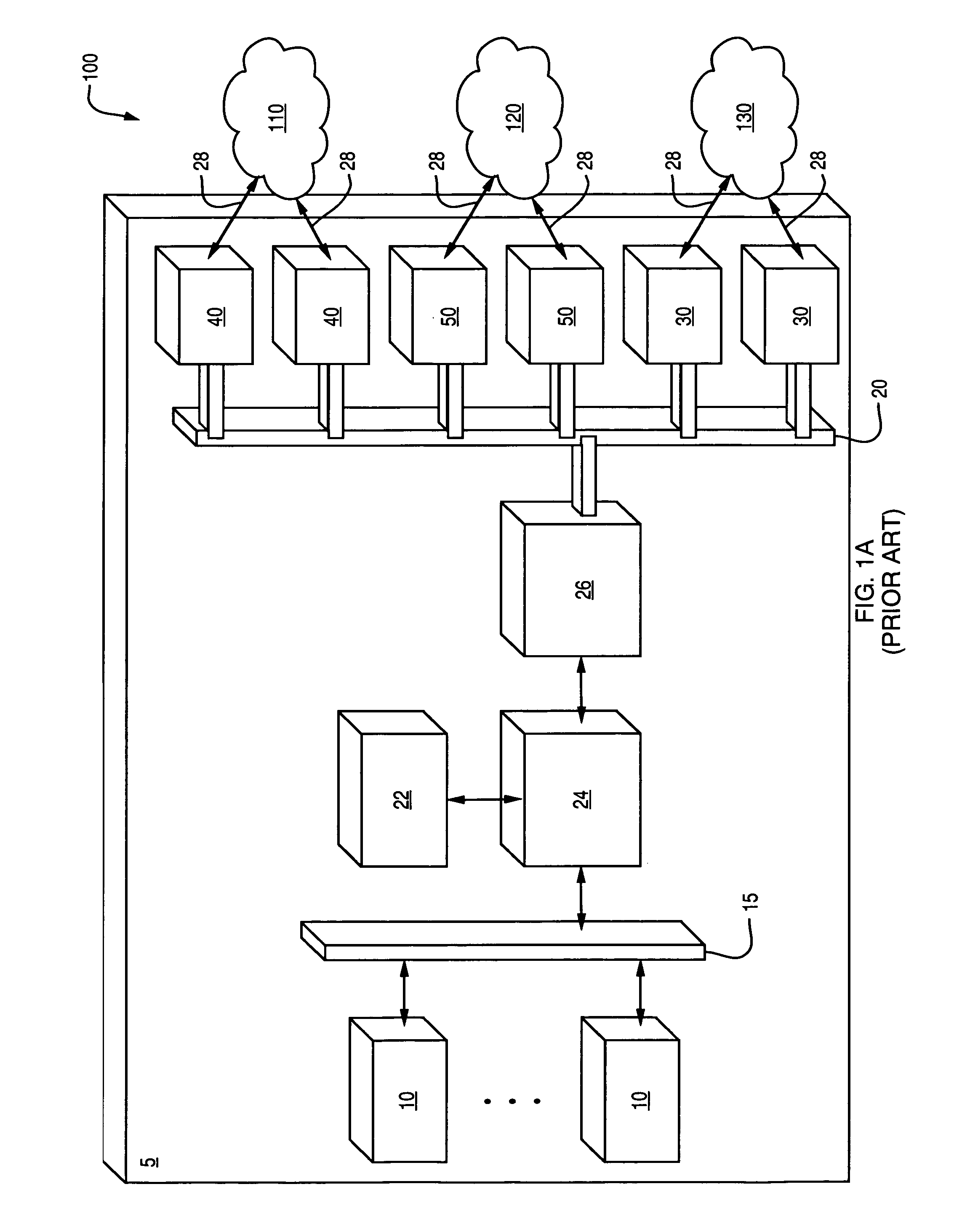
[0044]As shown in FIG. 1A, in a traditional (prior art) network system 100, a server 5 generally contains many components. These components, however, can logically be grouped into a few simple categories. As shown in the diagram, server 5 contains one or more CPUs 10, main memory 22, memory bridge 24, and I / O bridge 26. Server 5 communicates to networks such as Ethernet 110, Fibre Channel SAN 120, and IPC Network 130 through NICs 40, Fibre Channel Host Bus Adapters (HBAs) 50, and IPC adapters 30, respectively. These adapters or network cards (i.e., NICs 40, HBAs 50, or IPC adapters 30) are installed in server 5 and provide connectivity from the host CPUs 10 to networks 110, 120, 130.

[0045]As shown,...


PUM


Abstract

A shared I/O subsystem for a plurality of computer systems where a plurality of virtual I/O interfaces are communicatively coupled to the computer systems. Each of the computer systems includes a virtual adapter that communicates with one of the virtual I/O interfaces. The shared I/O subsystem also includes a plurality of I/O interfaces and a forwarding function. The forwarding function includes a plurality of forwarding table entries that logically arrange the shared I/O subsystem into one or more logical switches. Each of the logical switches communicatively couples one or more of the virtual I/O interfaces to one of the I/O interfaces. A logical switch receives a first I/O packet from one of the virtual I/O interfaces and directs the first I/O packet to at least one of the I/O interface and one or more of other ones of the virtual I/O interfaces. A logical switch also receives a second I/O packet from the I/O interface and directs the second I/O packet to one or more of the virtual I/O interfaces.

Description

CROSS REFERENCE TO RELATED APPLICATIONS[0001]This application claims priority to provisional patent application No. 60 / 380,071, entitled “Shared I / O Subsystem”, filed May 6, 2002, incorporated herein by reference.FIELD OF THE INVENTION[0002]The invention relates generally to computer network systems, and in particular, to shared computer network input / output subsystems.BACKGROUND OF INVENTION[0003]The Peripheral Component Interconnect (PCI), a local bus standard developed by Intel Corporation, has become the industry standard for providing all primary I / O functions for nearly all classes of computers and other peripheral devices. Some of the computers that employ the PCI architecture, for instance, range from a personal microcomputer (or desktop computer) at a lower entry-level to a server at an upper enterprise-level.[0004]However, while virtually all aspects of the computer technology, such as a processor or memory, advanced dramatically, especially over the past decade, the PCI s...

Claims


Application Information

Patent Timeline
IPC IPC(8): G06F15/173H04L12/56H04L29/06H04L29/08
CPCH04L29/06H04L45/742H04L49/358H04L67/1097H04L67/327H04L49/90H04L49/3009H04L49/602H04L69/329H04L69/22H04L69/18H04L69/14H04L67/63H04L9/40
Inventor MATTERS, TODDRIMMER, TODDMCCRORY, DUANECOYNE, JOSEPH DAVID
Owner TAHOE RES LTD
Why Eureka
Try Eureka