Leaking component link traffic engineering information

a technology of component link and traffic engineering information, applied in the field of packet network, can solve problems such as the overall performance decline of the network

Active Publication Date: 2011-03-08
DELL MARKETING CORP
View PDF8 Cites 102 Cited by
  • Summary
  • Abstract
  • Description
  • Claims
  • Application Information

AI Technical Summary

Problems solved by technology

Using shortest-path routing algorithms, it is difficult to guide specific traffic towards underutiliz...

Method used


Image

  • Leaking component link traffic engineering information
  • Leaking component link traffic engineering information
  • Leaking component link traffic engineering information

Examples


Embodiment Construction

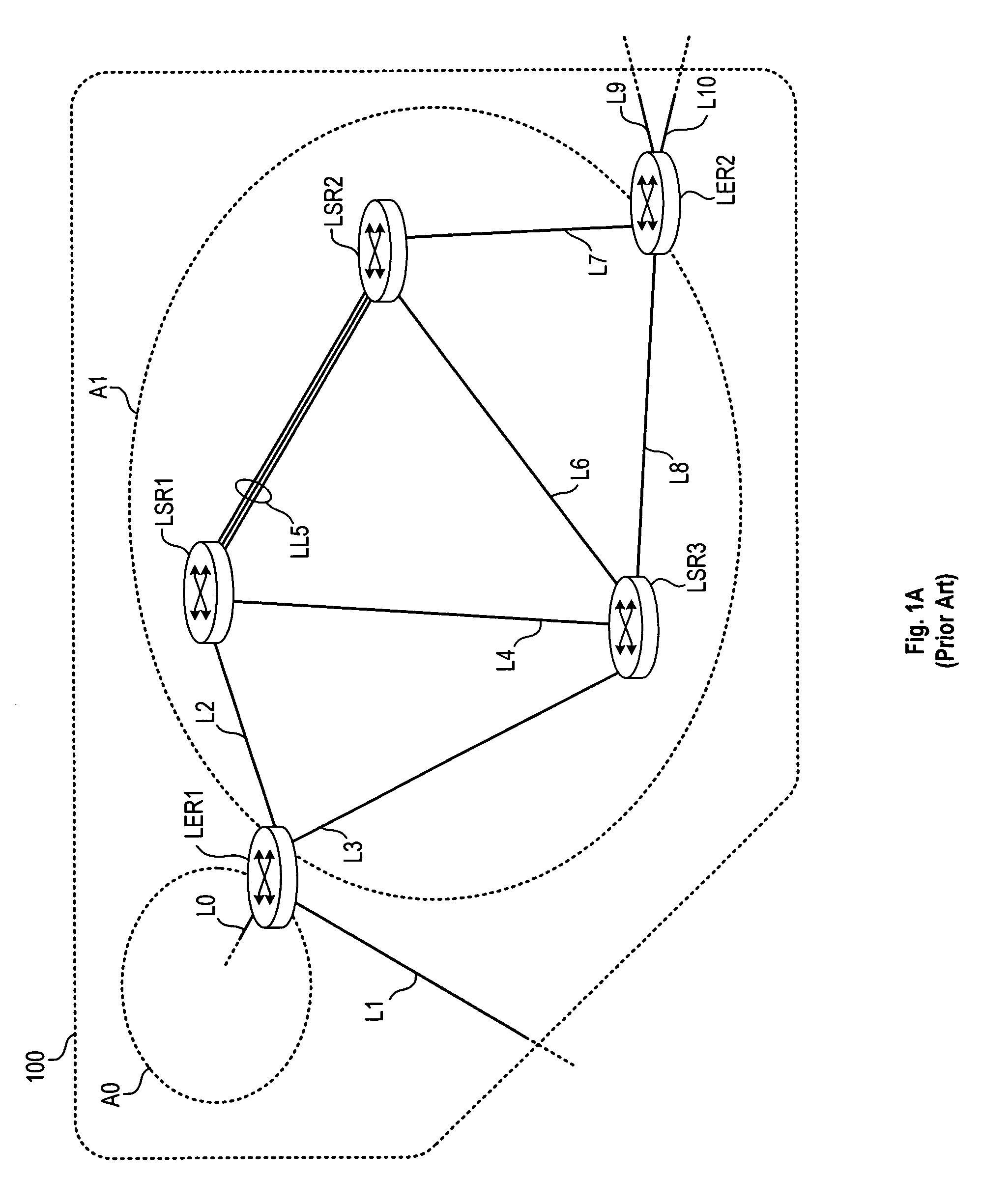
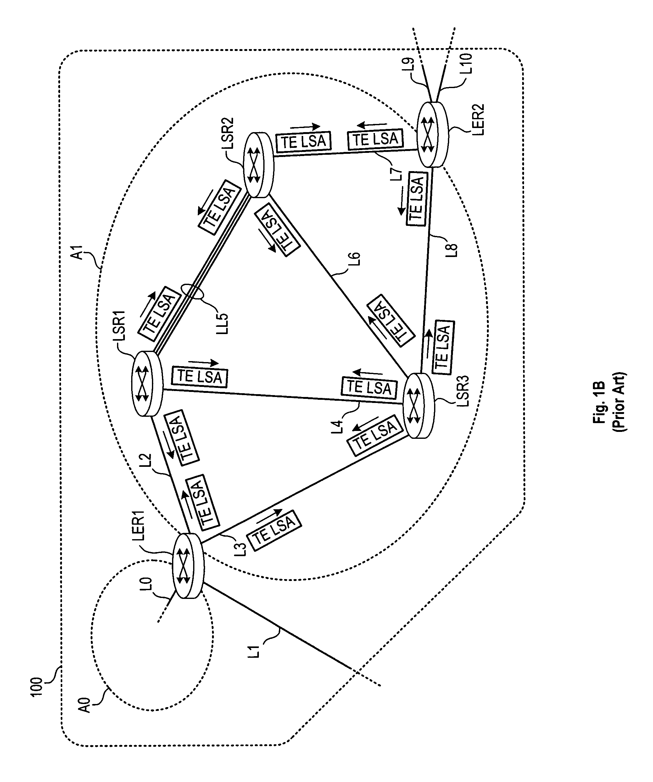
In the FIGS. 1A-1F embodiment, the LSP operates across a logical link LL5 between LSR1 and LSR2. Such a link can be formed between two adjacent switch / routers that have multiple physical channels (separate wires or fibers, separate wavelength channels, etc.) connecting the two. To create a logical link, the two adjacent switch / routers form a link aggregation group (LAG) that the two switch / routers manage between themselves. The routers then advertise the multiple physical channels to other devices in the area (e.g., using OSPF, IS-IS, etc.) as a single interface (e.g., using a MAC address from one of the interfaces). This advertised interface has a bandwidth capability that is roughly the sum of the bandwidths of the component links. The remainder of the bandwidth is spent in a small overhead exchange comprising link aggregation control protocol (LACP) packets that maintain the logical aggregation.

In operation, the transmitting end of a LAG link distributes the outbound packets for ...


PUM


Abstract

Traffic engineering using a label-switching protocol is enhanced for label-switched paths that traverse a logical link that is an aggregation of component links. In one embodiment, a label edge router is provided with information regarding the bandwidth capabilities and loading of the component links of a LAG. The label edge router is then allowed to set up paths that traverse a specific component link of a LAG, and reserve bandwidth on such a component link. Other traffic may continue to be distributed across the LAG membership.

Description

BACKGROUND1. Field of the InventionThe present disclosure relates generally to packet networks, and more particularly to the operation of traffic-engineered label-switched paths within such networks.2. Description of Related ArtIn a packet network, “nodes” or “routers” share network address information that allows each node or router to forward packets toward their respective destination networks. For networks defined using the Internet Protocol, each node is provisioned with a network address that identifies the particular network the system is on, and with a system or host address that uniquely identifies the node. These addresses are shared among neighboring nodes to allow each router to build a “tree” with itself as the root node and next-hop paths from itself to every address on the network.Routers use IP network and host addresses to forward routed traffic internally on a packet network according to an internal routing (or gateway) protocol (an “IGP”). Some common internal gat...

Claims


Application Information

Patent Timeline
IPC IPC(8): H04L12/28
CPCH04L45/026H04L45/10H04L45/302H04L47/724H04L47/748H04L47/762H04L2212/0025H04L45/50H04L2212/00
Inventor MANUR, RAJEEVSUBRAMANIAN, KRISHNAMURTHYZINJUVADIA, VISHAL
Owner DELL MARKETING CORP
Why Eureka
Try Eureka