Point to multi-point label switched paths with label distribution protocol

a label distribution and multi-point technology, applied in the field of computer network multi-cast traffic transmission, can solve the problems of rsvp scaling difficulty in service provider network, impracticality of deploying a second label distribution protocol to set up p2mp lsps,

Active Publication Date: 2011-05-10
JUMIPER NETWORKS INC
View PDF140 Cites 20 Cited by
  • Summary
  • Abstract
  • Description
  • Claims
  • Application Information

AI Technical Summary

Problems solved by technology

However, many VPN networks already use LDP, and deploying a second label distribution protocol to set up P2MP LSPs may be impractical.
Additionally, RSVP has difficulty scaling in service provider networks that include a large number of provider edge routers.

Method used


Image

  • Point to multi-point label switched paths with label distribution protocol
  • Point to multi-point label switched paths with label distribution protocol
  • Point to multi-point label switched paths with label distribution protocol

Examples


Embodiment Construction

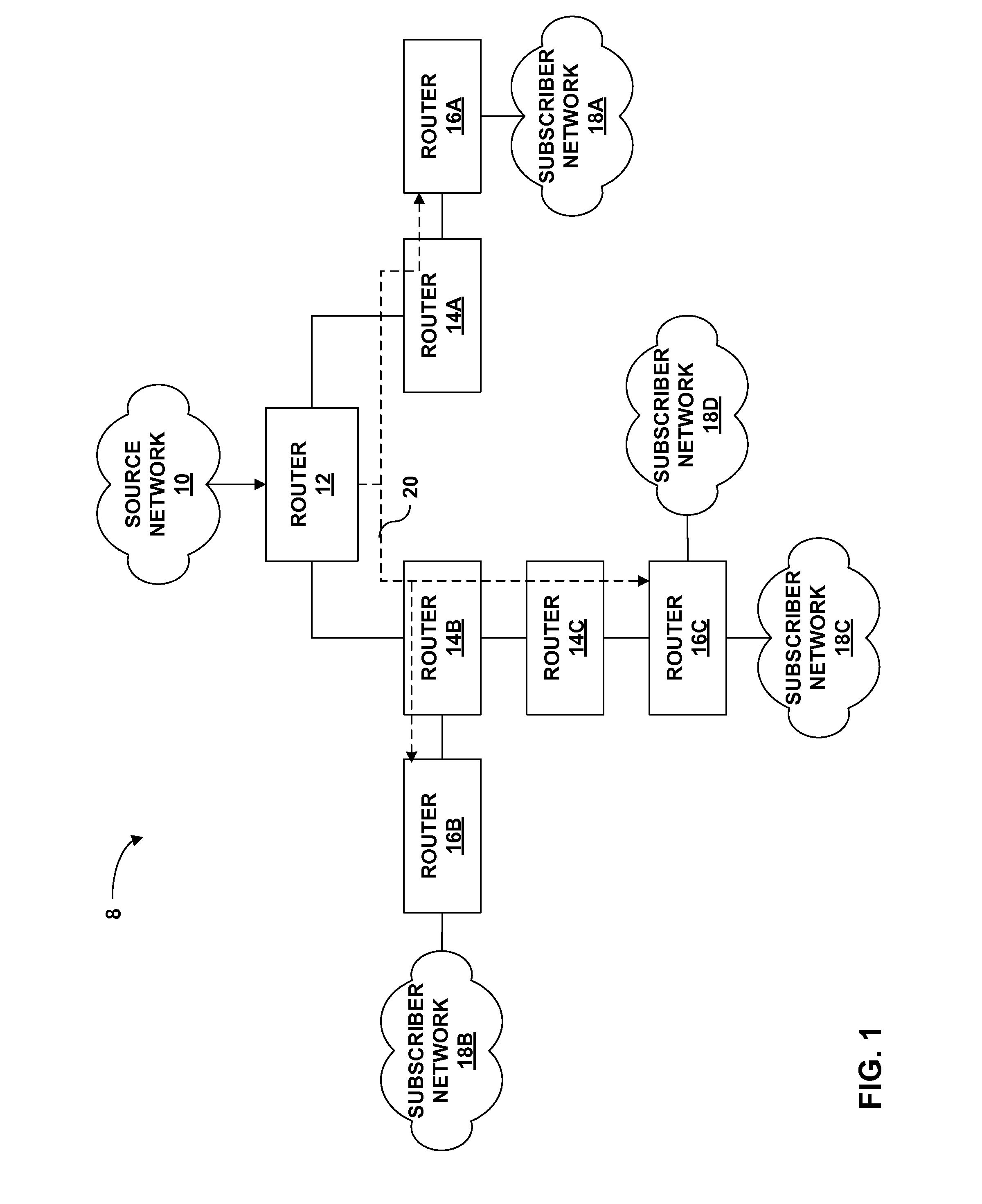
FIG. 1 is a block diagram illustrating an exemplary computer network 8 having a point to multi-point (P2MP) label switched path (LSP). Computer network 8 utilizes a protocol that has been extended to allow the protocol to establish the P2MP LSP. In this example, network 8 includes a P2MP LSP 20 established between a source router 12 (also referred to as a source network device) and destination routers 16A-16C (“routers 16”) (also referred to as destination network devices). In the example of FIG. 1, router 12 uses a protocol such as the label distribution protocol (LDP) that has been extended to establish P2MP LSP 20 to carry traffic between source network 10 and subscriber networks 18.

Source network 10 may comprise any public or private network or the Internet. As shown in FIG. 1, system 10 includes subscriber networks 18. Subscriber networks 18 may include local area networks (LANs) or wide area networks (WANs) that comprise a plurality of subscriber devices. The subscriber device...


PUM


Abstract

The label distribution protocol (LDP) is extended to set up a point to multi-point (P2MP) label switched path (LSP) across a computer network from a source network device to one or more destination network devices. LDP is extended to create a P2MP label map message containing a label and a P2MP forwarding equivalence class (FEC) element having a root node address and an identifier. The P2MP FEC element may, for example, associate an address of the root node of the P2MP LSP with an opaque identifier. The P2MP FEC element uniquely identifies the P2MP LSP. The P2MP FEC element may be advertised with a label in a P2MP label map message. A source network device or the destination network devices may initiate setup and teardown of the P2MP LSP. The P2MP label map messages may be propagated from the destination network devices to the source network device.

Description

TECHNICAL FIELDThe invention relates to computer networks and, more particularly, to transmission of multicast traffic within a computer network.BACKGROUNDA computer network is a collection of interconnected computing devices that exchange data and share resources. In a packet-based network, such as the Internet, the computing devices communicate data by dividing the data into small blocks called packets. The packets are individually routed across the network from a source device to a destination device. The destination device extracts the data from the packets and assembles the data into its original form. Dividing the data into packets enables the source device to resend only those individual packets that may be lost during transmission.Routing devices within the network, often referred to as routers, maintain routing information that describe available routes through the network. Upon receiving an incoming packet, the router examines information within the packet and forwards the...

Claims


Application Information

Patent Timeline
Patent Type & Authority Patents(United States)
IPC IPC(8): H04L12/28H04L12/56
CPCH04L45/00H04L45/16H04L45/507H04L45/50H04L45/302
Inventor MINEI, INAKOMPELLA, KIREETISHETH, NISCHAL
Owner JUMIPER NETWORKS INC
Why Eureka
Try Eureka