
Carabiner having dual gates and associated methods

a carabiner and dual gate technology, applied in the field of carabiners, can solve the problems of compromising the strength of the carabiner, affecting the service life of the carabiner,

Inactive Publication Date: 2011-05-24
ROCK EXOTICA
View PDF35 Cites 32 Cited by
  • Summary
  • Abstract
  • Description
  • Claims
  • Application Information

AI Technical Summary

Benefits of technology

The dual-gate carabiner design enhances safety by preventing accidental opening, maintaining the carabiner's closed state under various loads and forces, ensuring the rope remains clipped, even during falls or when operated with one hand, and reduces the risk of accidental unlocking due to twisting or foreign material interference.

Problems solved by technology

For example, a non-locking carabiner is more susceptible to having the gate pushed open, and becoming unclipped.
The gate of a non-locking carabiner may also be inadvertently opened when the carabiner is pushed against a rock face or other object.
This is dangerous, not only because the carabiner may become unclipped and detached from the object to which it is attached or a rope passing through the carabiner may become unclipped and detached, but also because the strength of the carabiner is compromised with the gate in an open position.
The rope may become unclipped and detached from the carabiner, causing the climber to fall further.
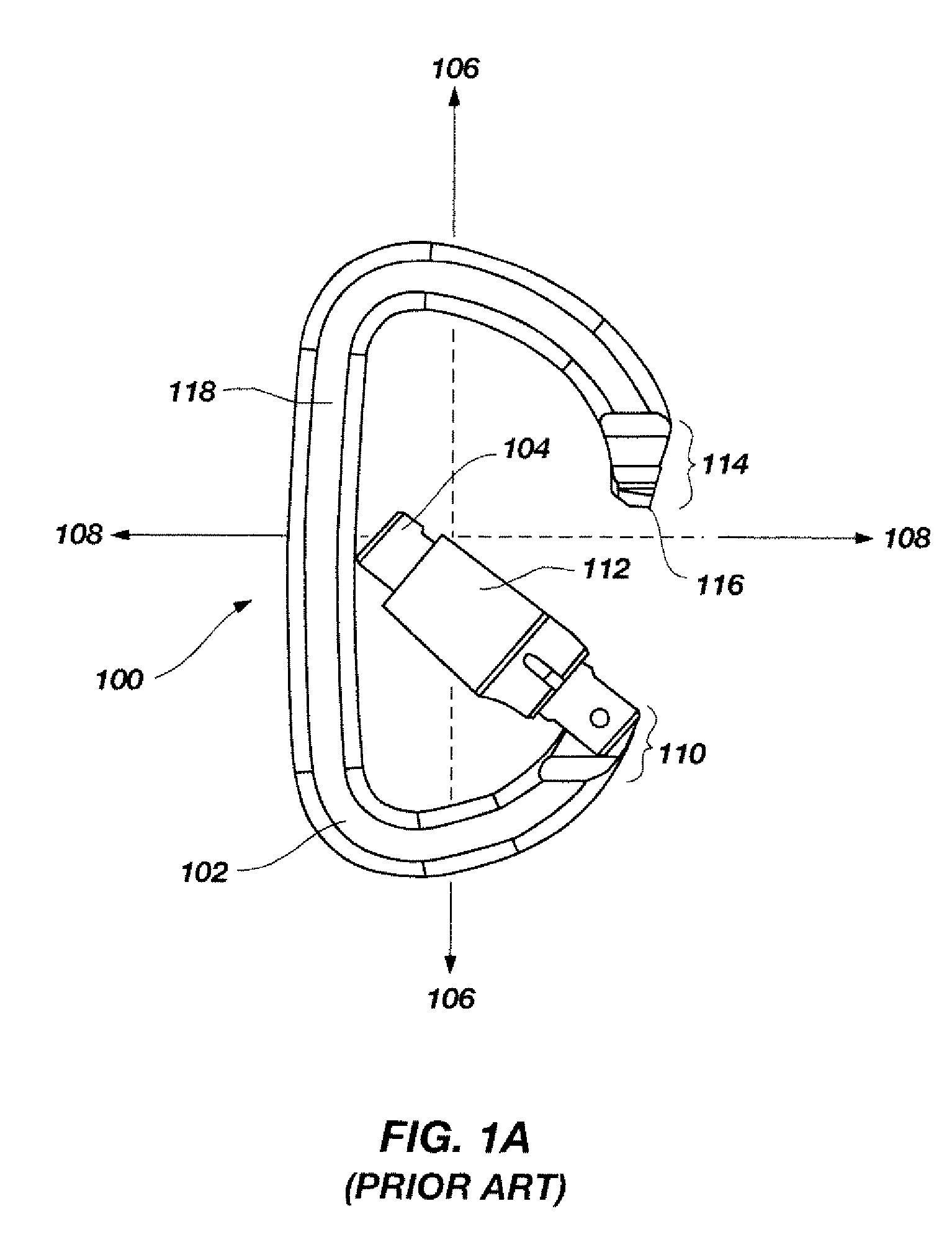
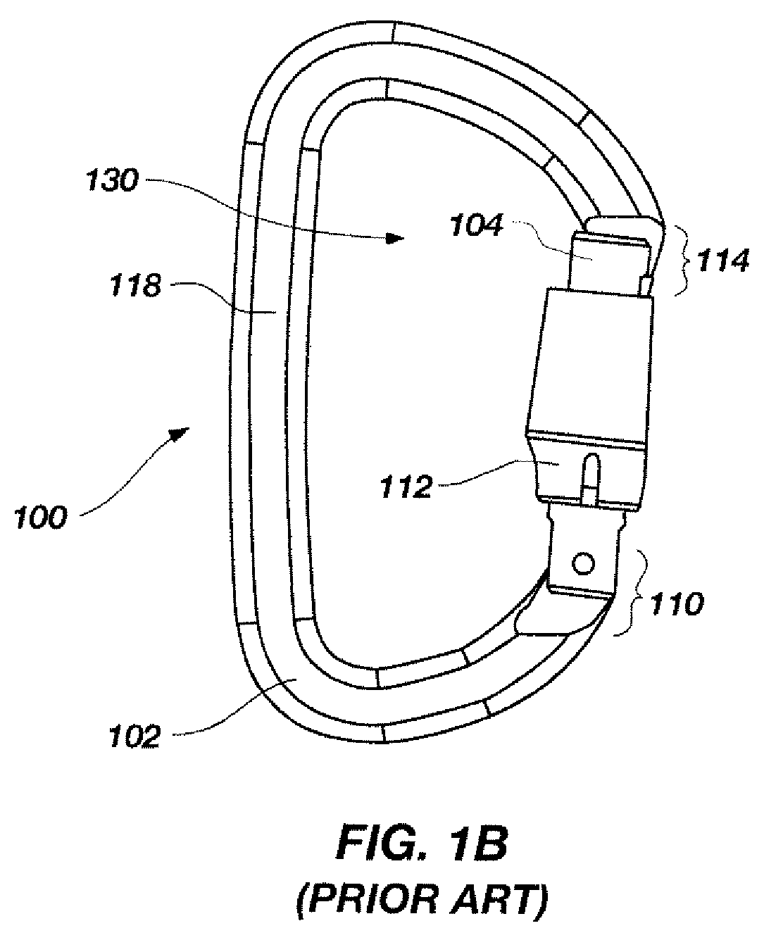
Even with the use of a locking carabiner, the sleeve 112 may be a point of failure.
Conventional locking sleeves have been known to fail under a body weight load, enabling the gate to swing open.
With an open gate, the carabiner may fail under a lesser load, or become unclipped and detached.
Another disadvantage of a conventional locking carabiner is that an additional twisting motion is generally required to release the sleeve 112, in order to open the gate.
This may be undesirable or even impossible to effect in a number of situations, for example when a rock climber is dangling from a cliff face with only one free hand, and would like to clip his or her rope through the carabiner.
The twisting release motion may also be undesirable because the rope or another object may rub against the sleeve and twist it, resulting in an accidentally unlocked carabiner.

Method used


Image

  • Carabiner having dual gates and associated methods
  • Carabiner having dual gates and associated methods
  • Carabiner having dual gates and associated methods

Examples


Embodiment Construction

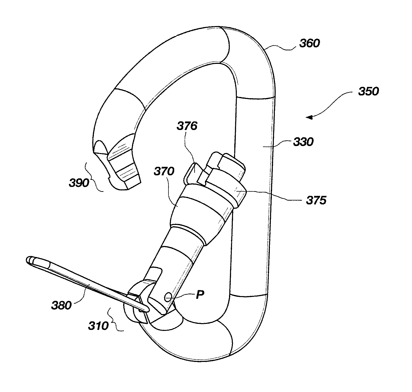
[0025]The present invention, in a number of embodiments, includes carabiners having a dual gate that may be used, for example, to retain a rope therewithin. As known in the art, the body of the carabiners of the present invention may be formed from a variety of metals and alloys, such as aluminum alloys and steel. The body of the carabiners may be shaped by bending into the desired shape, followed by stamping or machining to impart a desired cross-sectional configuration, and heat treating, if necessary or desired, to increase the strength or alter other material properties thereof. The term “generally C-shaped,” as used herein, encompasses any style or configuration of carabiner body, including, by way of example and not limitation, oval, D-shaped, offset D-shaped, pear shaped and twisted. In the detailed description, which follows, like features and elements in the several embodiments are identified in the drawings with the same or similar reference numerals for the convenience of...


PUM


Abstract

Various embodiments for carabiners include two gates. The carabiners include a C-shaped body having a nose region and an end region. An inner gate is configured to pivot about the end region from a closed position in contact with the nose region, and an open position, wherein the inner gate pivots toward the spine of the C-shaped body. An outer gate is configured to pivot about the end region from a closed position in contact with the nose region, and an open position, extending away from the C-shaped body. The inner and the outer gate may each comprise wire gates, alternatively one gate may comprise a generally cylindrical gate and the other gate may comprise a wire gate. Methods include preventing a carabiner from opening.

Description

CROSS-REFERENCE TO RELATED APPLICATIONS[0001]This application claims the benefit of U.S. Provisional Application Ser. No. 60 / 819,778 filed Jul. 10, 2006, the disclosure of which is incorporated in its entirety herein by this reference.FIELD OF THE INVENTION[0002]The present invention relates to a carabiner. More particularly, the present invention relates to a carabiner having dual gates.BACKGROUND[0003]Carabiners are used for various applications in many different activities. Carabiners are typically associated with outdoor recreational activities, such as rock climbing, mountaineering, mountain rescue work, and sailing. However, carabiners are also employed in applications such as rescue work in urban and industrial settings, safety restraints in urban and industrial settings, law enforcement work, and military applications among many other applications.[0004]Conventionally, a carabiner has a ring, or C-shaped body, having a gate, which may be opened to insert a rope, sling, or a ...

Claims


Application Information

Patent Timeline
Patent Type & Authority Patents(United States)
IPC IPC(8): F16B45/02
CPCF16B45/02Y10T24/45319Y10T24/45272Y10T24/45435Y10T24/45236Y10T24/45445F16B45/023F16B45/027F16B45/036
Inventor THOMPSON, ROCKE P.
Owner ROCK EXOTICA
Learn More