
Single arm row cleaner

a single arm and row cleaner technology, applied in the field of improved row cleaning, can solve the problem of difficult to attach a suitable row cleaner thereto

Inactive Publication Date: 2011-05-24
MARTIN HOWARD D +1
View PDF13 Cites 74 Cited by
  • Summary
  • Abstract
  • Description
  • Claims
  • Application Information

AI Technical Summary

Benefits of technology

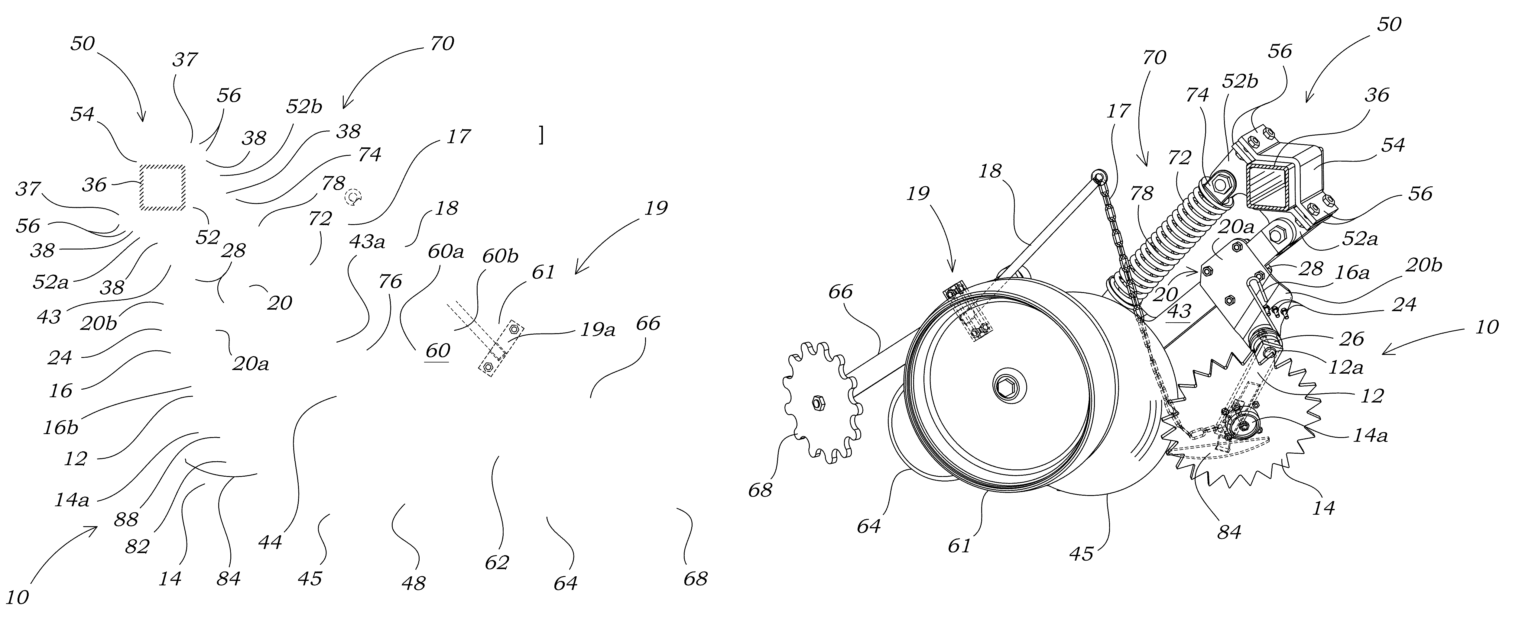
[0018]FIG. 5A provides a side view of the assembly shown in FIG. 3 with the furrow forming assembly raised to transport position.

Problems solved by technology

The narrow spacing between the opener units and the “boxed in” configuration of the frame of the John Deere 750 drill have to date made it difficult to attach a suitable row cleaner thereto.

Method used


Image

  • Single arm row cleaner
  • Single arm row cleaner
  • Single arm row cleaner

Examples


Embodiment Construction

—LISTING OF ELEMENTS

[0022]

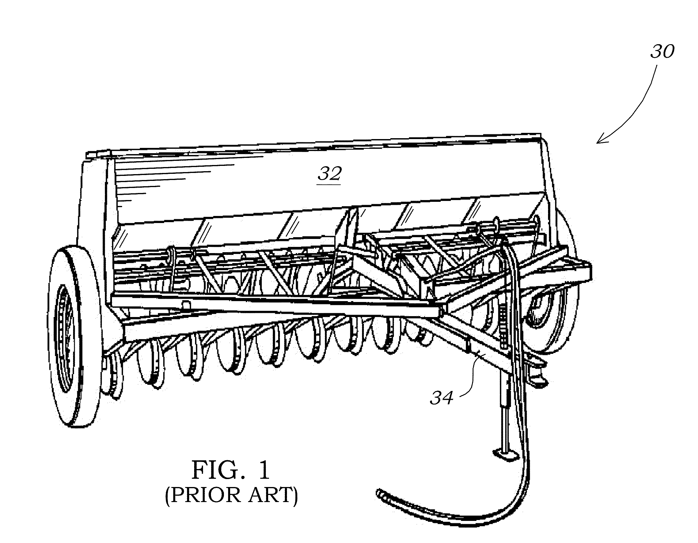
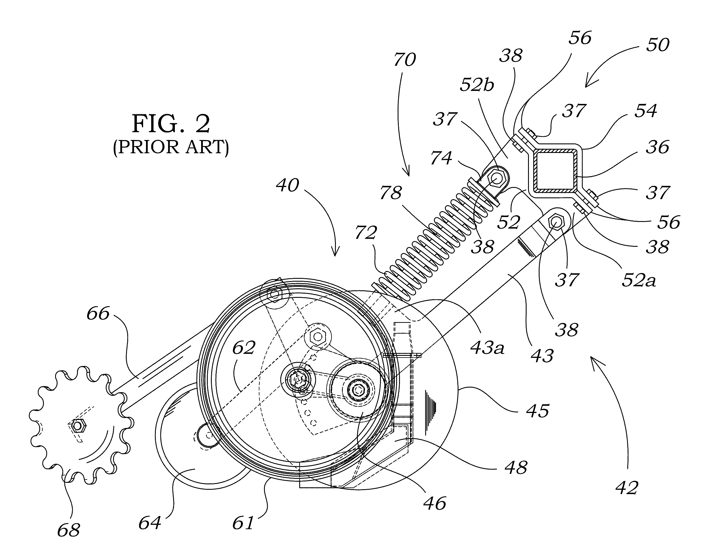
ElementElement DescriptionNumberSingle arm row cleaner10Row cleaner arm12Mounting aperture12aWheel aperture12bPin aperture12cConnector aperture12dRow cleaner wheel14Row cleaner wheel hub14aBiasing member16Adjustment portion16aArm engaging portion16bConnector17Lever arm18Lever arm bracket19Bracket side19aBracket bolt19bBracket nut19cMounting saddle20Body20aFront portion20bAperture22Biasing member retainer24Mandrel26Mounting saddle connector28Grain drill30Hopper32Hitch34Toolbar36Nut37Bolt38Furrow forming assembly40Opener arm assembly42Main arm43Down pressure mount43aMain arm lower end44Opener45Disc hub46Seed delivery member48Bracket assembly50Anchor52Main arm support52aDown pressure support52bCap54Flange56Depth regulator assembly frame60Press wheel arm mount60aClosing wheel arm mount60bDepth regulator61Press wheel arm62Press wheel64Closing wheel arm66Closing wheel68Down pressure assembly70Down pressure biasing member72Down pressure bracket mount74Down pressur...


PUM


Abstract

A single arm row cleaner unit mountable to a grain drill opener arm includes a row cleaner arm and a mounting saddle. The mounting saddle is generally configured for attachment to a main arm of a furrow forming assembly. A row cleaner arm may be pivotally attached to the mounting saddle about a mandrel, and a row cleaner wheel may be pivotally mounted to the row cleaner arm. A biasing member may be positioned adjacent the mandrel to engage the row cleaner arm and a biasing member retainer, which may be affixed to the mounting saddle. A deflector may be positioned adjacent the row cleaner wheel and biased there against. A connector and lever arm may be used to communicate forces from a closing wheel arm to the row cleaner wheel for adequate clearance of the row cleaner wheel during transport of the grain drill.

Description

CROSS REFERENCE TO RELATED APPLICATIONS[0001]This application claims the filing benefit under 35 U.S.C. §119(e) of provisional U.S. Pat. App. Ser. No. 61 / 133,867 filed on Jul. 3, 2008.FIELD OF THE INVENTION[0002]The methods and apparatuses described herein are generally applicable to the field of agricultural equipment. The embodiments shown and described herein are more particularly for improved row cleaning for delivery of seed or fertilizer. Although in no way limiting, the present disclosure is particularly suited for minimum or no-till conditions.STATEMENT REGARDING FEDERALLY SPONSORED RESEARCH OR DEVELOPMENT[0003]No federal funds were used to develop or create the invention disclosed and described in the patent application.REFERENCE TO SEQUENCE LISTING, A TABLE, OR A COMPUTER PROGRAM LISTING COMPACT DISK APPENDIX[0004]Not Applicable.AUTHORIZATION PURSUANT TO 37 C.F.R. §1.171 (d)[0005]A portion of the disclosure of this patent document contains material which is subject to copy...

Claims


Application Information

Patent Timeline
IPC IPC(8): A01B15/16A01C7/18A01C5/00A01B23/06A01B21/02
CPCA01C5/064A01B35/16A01C7/006Y02P60/20
Inventor MARTIN, HOWARD D.MARTIN, RONALD S.
Owner MARTIN HOWARD D
Learn More