Sealing trumpet for a post-tension anchorage system

a post-tension anchorage and sealing trumpet technology, applied in the direction of couplings, rod connections, manufacturing tools, etc., can solve the problems of weak structural concrete, inability to carry significant tensile loads, method does not use the full potentialities of concrete,

Active Publication Date: 2011-05-31
SORKIN FELIX L
View PDF18 Cites 36 Cited by
  • Summary
  • Abstract
  • Description
  • Claims
  • Application Information

AI Technical Summary

Benefits of technology

[0033]The trumpet has a length of no more than two inches in the preferred embodiment of the present invention. The annular seal is positioned inwardly of an end of the trumpet opposite the anchor body. In the preferred embodiment of the present invention, the annular seal is integral with the trumpet. This polymeric encapsulation is in liquid-tight sealing relationship with an exterior surface of the anchor body.

Problems solved by technology

On the other hand, structural concrete, though quite capable of carrying almost any compressive load, is weak in carrying significant tensile loads.
Structures of reinforced concrete may be constructed with load-bearing walls, but this method does not use the full potentialities of the concrete.
This procedure is somewhat difficult since the tendon can have a considerable length and since the use of tension forces can create a somewhat unreliable connection between the wedges and the tendon.
One of the problems with conventional dead-end anchorages is that the sheathing over the tendon has a tendency to shrink over time.
The problem that affects many anchorage system is the inability to effectively prevent liquid intrusion into this area of the unsheathed portion.
In certain circumstances, these tubes are sometimes improperly installed and, at best, are simply an additional component that needs to be associated with the post-tension system.
As such, it adds additional costs and can require additional labor associated with the installation of the sealing tube.

Method used


Image

  • Sealing trumpet for a post-tension anchorage system
  • Sealing trumpet for a post-tension anchorage system
  • Sealing trumpet for a post-tension anchorage system

Examples


Embodiment Construction

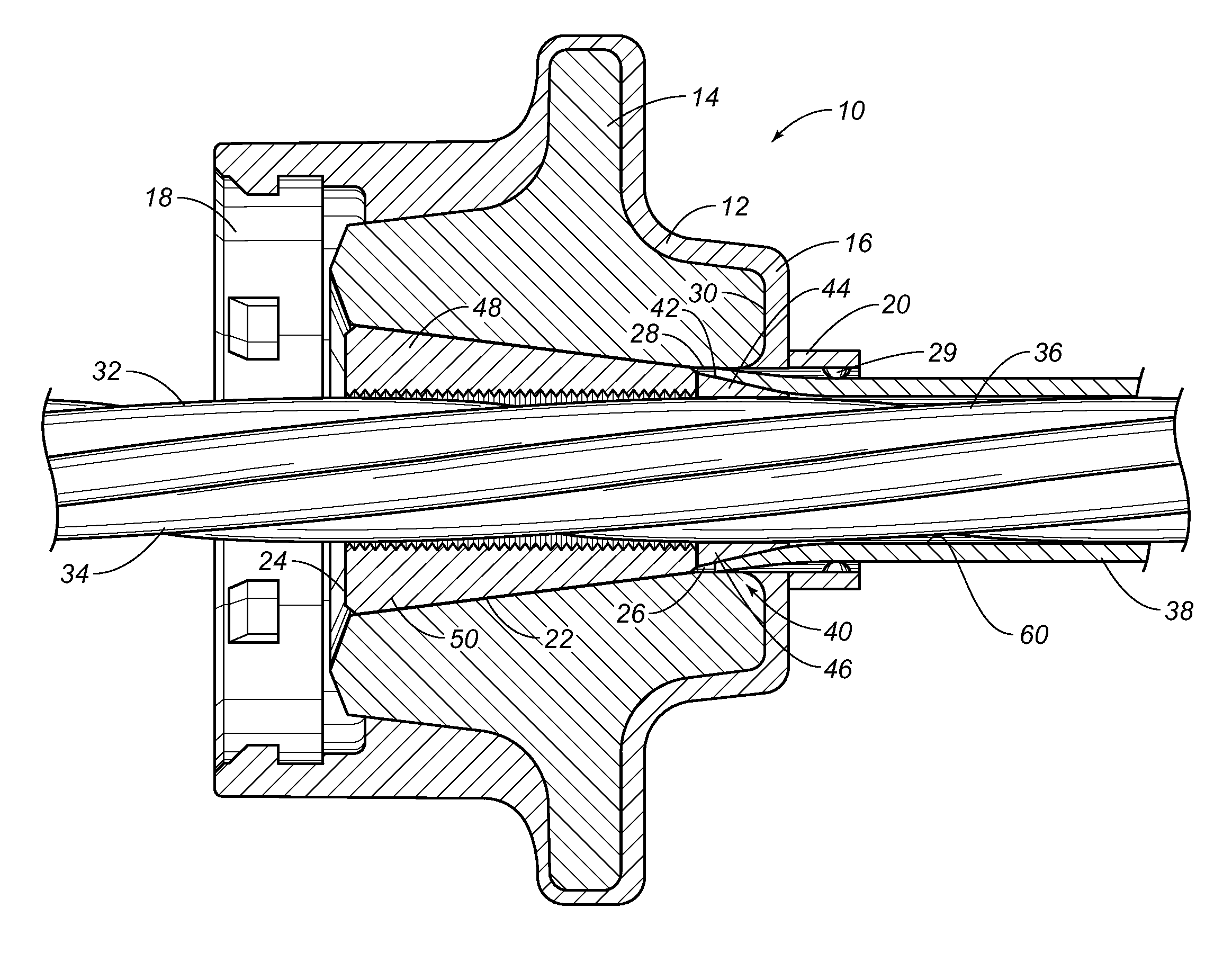
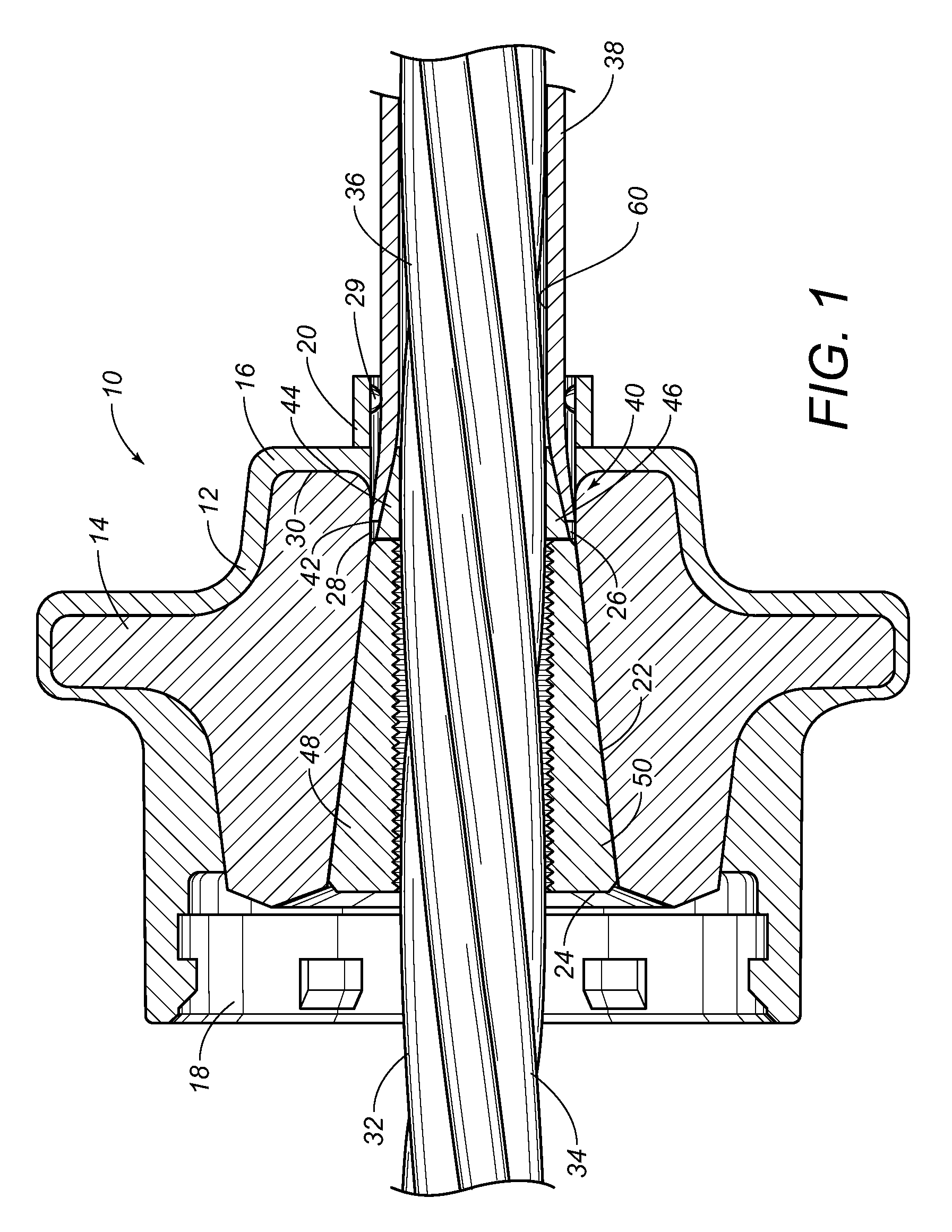
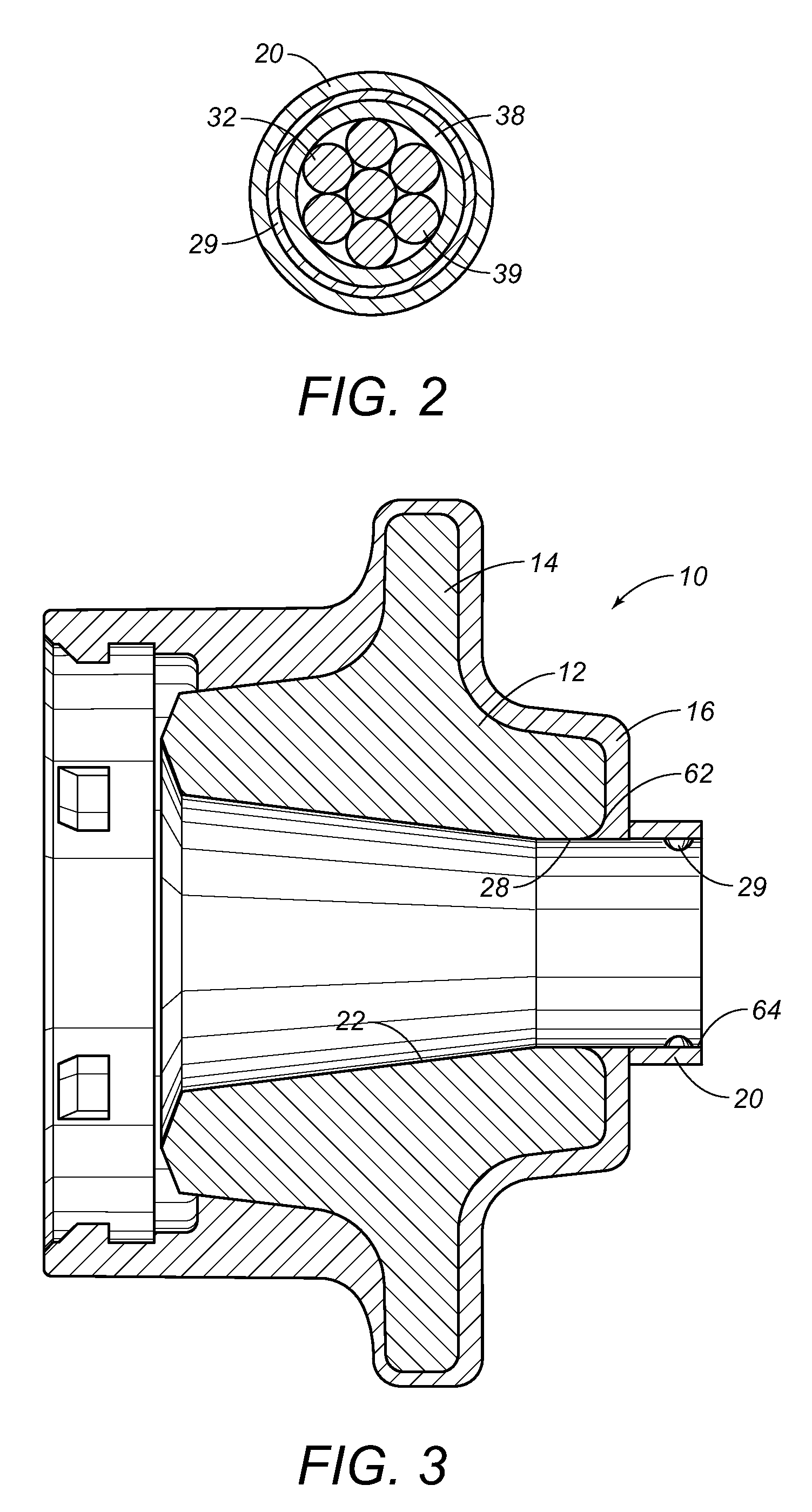
[0038]Referring to FIG. 1, there is shown the apparatus 10 for resisting the shrinkage of a sheathing of a tendon in a post-tension anchor system. In particular, the apparatus 10 shows the dead-end anchorage 12. The dead-end anchorage 12 includes an anchor member 14 with a polymeric encapsulation 16 extending thereover and therearound. A cap-receiving opening 18 is formed at one end of the polymeric encapsulation 16. A trumpet 20 is formed at the opposite end of the polymeric encapsulation 16. The trumpet 20 is a tubular section that extends outwardly of the end of the dead-end anchorage 12 for a short distance. The anchor member 14 is a steel anchor. The anchor member 14 has a cavity 22 formed in an interior thereof. The cavity 22 has tapered walls having a wide end 24 and a narrow end 26. The wide end 24 opens at an end of the anchor member 14. The narrow end 26 opens on the interior of the cavity 22. A passageway 28 extends from the narrow end 26 of cavity 22 to the opposite end ...


PUM


Abstract

An anchorage for post-tension system has an anchor body with an interior passageway, a polymeric encapsulation extending over the anchor body so as to define a trumpet extending outwardly on one side of the anchor body, and an annular seal formed so as to extend inwardly relative to a wall of the trumpet. The annular seal is in liquid-tight sealing relation with an outer surface of a tendon extending through the interior passageway. A fixing element is formed within the interior passageway so as to fix a position of the sheathing on the tendon.

Description

CROSS-REFERENCE TO RELATED APPLICATIONS[0001]The present invention is a continuation-in-part of U.S. application Ser. No. 11 / 861,185, filed on 25 Sep. 2007 and entitled “Apparatus for Preventing Shrinkage of a Sheathing over a Tendon”, presently pending.STATEMENT REGARDING FEDERALLY SPONSORED RESEARCH OR DEVELOPMENT[0002]Not applicable.NAMES OF THE PARTIES TO A JOINT RESEARCH AGREEMENT[0003]Not applicable.INCORPORATION-BY-REFERENCE OF MATERIALS SUBMITTED ON A COMPACT DISC[0004]Not applicable.BACKGROUND OF THE INVENTION[0005]1. Field of the Invention[0006]The present invention relates to post tension anchor systems. More particularly, the present invention the present invention relates to seals as used within polymeric encapsulated anchor bodies. More particularly, the present invention the present invention relates to apparatus used to prevent shrinkage of a sheathing that extends over a tendon.[0007]2. Description of Related Art[0008]Including Information Disclosed Under 37 CFR 1.9...

Claims


Application Information

Patent Timeline
Patent Type & Authority Patents(United States)
IPC IPC(8): E04C5/08
CPCE04C5/10E04C5/122E04G21/12Y10T403/7051Y10T403/7064Y10T403/7054Y10T403/5793
Inventor SORKIN, FELIX L.
Owner SORKIN FELIX L
Why Eureka
Try Eureka