
Method of controlling recording of optical disc device and optical disc device using the method

a technology of optical disc and recording method, which is applied in the direction of digital signal error detection/correction, instruments, recording signal processing, etc., can solve the problems of abnormal data, data writing may continue without correcting for errors, and desired data may not be completely formed on the labeled surface of the optical dis

Inactive Publication Date: 2011-05-31
SAMSUNG ELECTRONICS CO LTD
View PDF8 Cites 0 Cited by
  • Summary
  • Abstract
  • Description
  • Claims
  • Application Information

AI Technical Summary

Benefits of technology

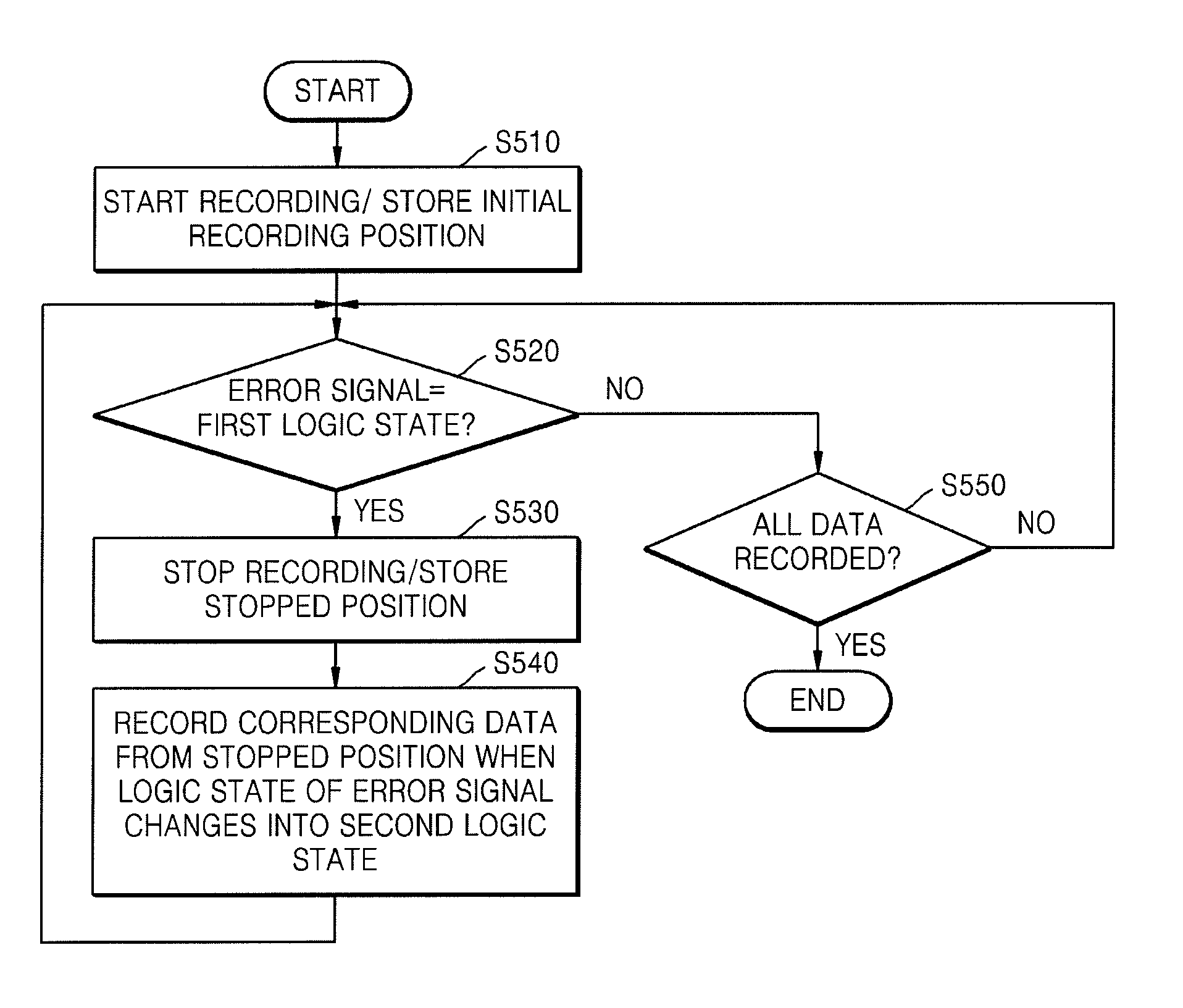
The present invention provides an optical disc device that can stop recording when a recording error occurs and start again from a stopped position when the error is corrected. This allows for more efficient recording and reduces the likelihood of errors during recording. The device includes a controller that controls the record unit to stop recording when an error occurs and prepares to record from the stopped position when the error is corrected. The device also includes an error detecting unit that outputs an error signal with different logic states depending on the type of error. The controller can delete data already recorded when an error occurs during recording. The invention also provides a method for controlling recording of an optical disc device that stops recording when an error occurs and records corresponding data from a stopped position when the error is removed. The method includes storing an initial recording position and a stopped position. Overall, the invention improves the accuracy and efficiency of recording on optical discs.

Problems solved by technology

However, if an error occurs when writing the data, for example, when light is not precisely focused on the labeled surface of the optical disc, data writing may continue on without correcting for the error.
Thus, in case where an error is generated during recording, abnormal data occurs at a corresponding portion of the optical disc.
As a result, the desired data may not be completely formed on the labeled surface of the optical disc.

Method used


Image

  • Method of controlling recording of optical disc device and optical disc device using the method
  • Method of controlling recording of optical disc device and optical disc device using the method
  • Method of controlling recording of optical disc device and optical disc device using the method

Examples


Embodiment Construction

[0031]In describing exemplary embodiments of the present disclosure illustrated in the drawings, specific terminology is employed for sake of clarity. However, the present disclosure is not intended to be limited to the specific terminology so selected, and it is to be understood that each specific element includes all technical equivalents which operate in a similar manner. Like reference numerals in the drawings may denote like elements.

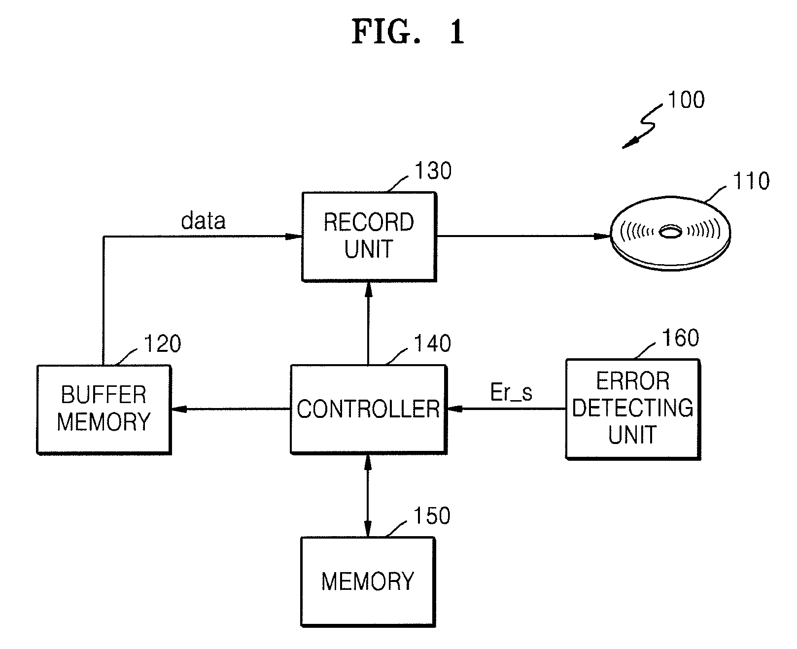
[0032]FIG. 1 is a block diagram of an optical disc device 100 according to an exemplary embodiment of the present general inventive concept.

[0033]Referring to FIG. 1, the optical disc device 100 may include an optical disc 110, a buffer memory 120, a record unit 130 and a controller 140.

[0034]The optical disc 110 may have at least one circular track. Alternatively, the optical disc 110 may have at least one spiral track. The present general inventive concept can be applied to a case where the optical disc 110 has a spiral track as well as a case wh...


PUM

PropertyMeasurementUnit
recording voltageaaaaaaaaaa
timeaaaaaaaaaa

Abstract

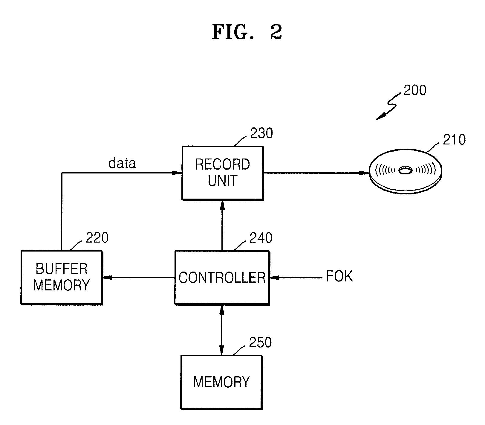
A method of controlling recording of an optical disc device and an optical disc device using the method. The optical disc device performs recording of data on a labeled surface of the optical disc. The device includes a buffer memory, a record unit and a controller. The buffer memory stores data and the record unit records data on the labeled surface of the optical disc from the buffer memory. The controller controls the record unit such that when a recording error occurs, the recording is stopped and when the error is corrected, data is recorded from a stopped position.

Description

CROSS-REFERENCE TO RELATED APPLICATION[0001]This application claims the benefit of Korean Patent Application No. 10-2007-0089950, filed on Sep. 5, 2007, in the Korean Intellectual Property Office, the disclosure of which is incorporated herein in its entirety by reference.BACKGROUND OF THE INVENTION[0002]1. Technical Field[0003]The present general inventive concept relates to an optical disc device, and more particularly, to a method of controlling recording of an optical disc device and an optical disc device using the method.[0004]2. Discussion of the Related Art[0005]Conventional optical disc devices, such as compact disc players, laserdisc players and video compact disc players, reproduce images and / or sounds recorded on an optical disc to output the reproduced images and / or sounds through a display and / or speaker.[0006]These optical disc devices use light in order to read or write data. To correctly record data on or read data from an optical disc, light may be precisely focuse...

Claims


Application Information

Patent Timeline
Patent Type & Authority Patents(United States)
IPC IPC(8): G11B7/00
CPCG11B20/10527G11B20/18G11B2220/2537G11B2020/1062G11B23/40
Inventor YUN, SEOK-MINKIM, SOO-YONG
Owner SAMSUNG ELECTRONICS CO LTD
Learn More