Laser power controlling method for recording data and related apparatus

a technology of power control and data, applied in the field of laser control method, can solve the problems of unstable write power, unable to characterize other information about the laser power, and the signal to noise ratio (snr) of the reflected pulse level utilized to adjust the optimum power

Inactive Publication Date: 2006-11-16
MEDIATEK INC
View PDF7 Cites 5 Cited by
  • Summary
  • Abstract
  • Description
  • Claims
  • Application Information

AI Technical Summary

Benefits of technology

[0001] The present invention relates to a laser controlling method and a related apparatus, and more particularly, to a laser power controlling method and apparatus capable of stopping recording of data for adjusting the laser power and restarting recording of data.

Problems solved by technology

Unfortunately, different compact discs have varying energy absorption characteristics of the laser beam due to different properties of the recording layers.
This is necessary due to inconsistent characteristics of the compact disc itself, for example, dust on the optical disc, an unexpected influence making the write power unstable, or a temperature variance influencing operation of the pick-up head.
However, the obtained optimum power fails to characterize other information about the laser power, such as the overdrive (OD) power and OD length, when performing the related art OPC procedure.
When performing the conventional OPC procedure, the temperature or the delay of a transmitting circuit of the optical disc recorder will influence the OD power and distort the result of the OPC procedure.
Additionally, during the ROPC procedure, the Signal to Noise Ration (SNR) of the reflected pulse level utilized to adjust the optimum power worsens when the optical disc recorder operates at a high recording speed.
Furthermore, the reflected pulse level may also be incorrectly detected because of environment factors, such as the tilt of the optical disc.
The ROPC procedure, therefore, adjusts the optimum power incorrectly.

Method used


Image

  • Laser power controlling method for recording data and related apparatus
  • Laser power controlling method for recording data and related apparatus
  • Laser power controlling method for recording data and related apparatus

Examples


Embodiment Construction

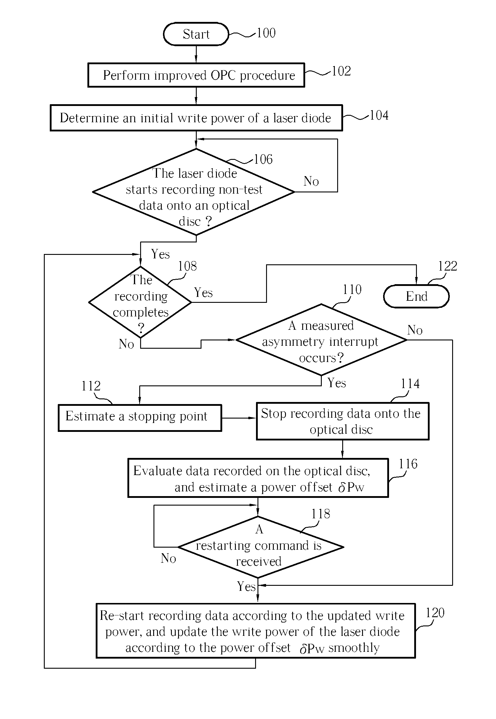
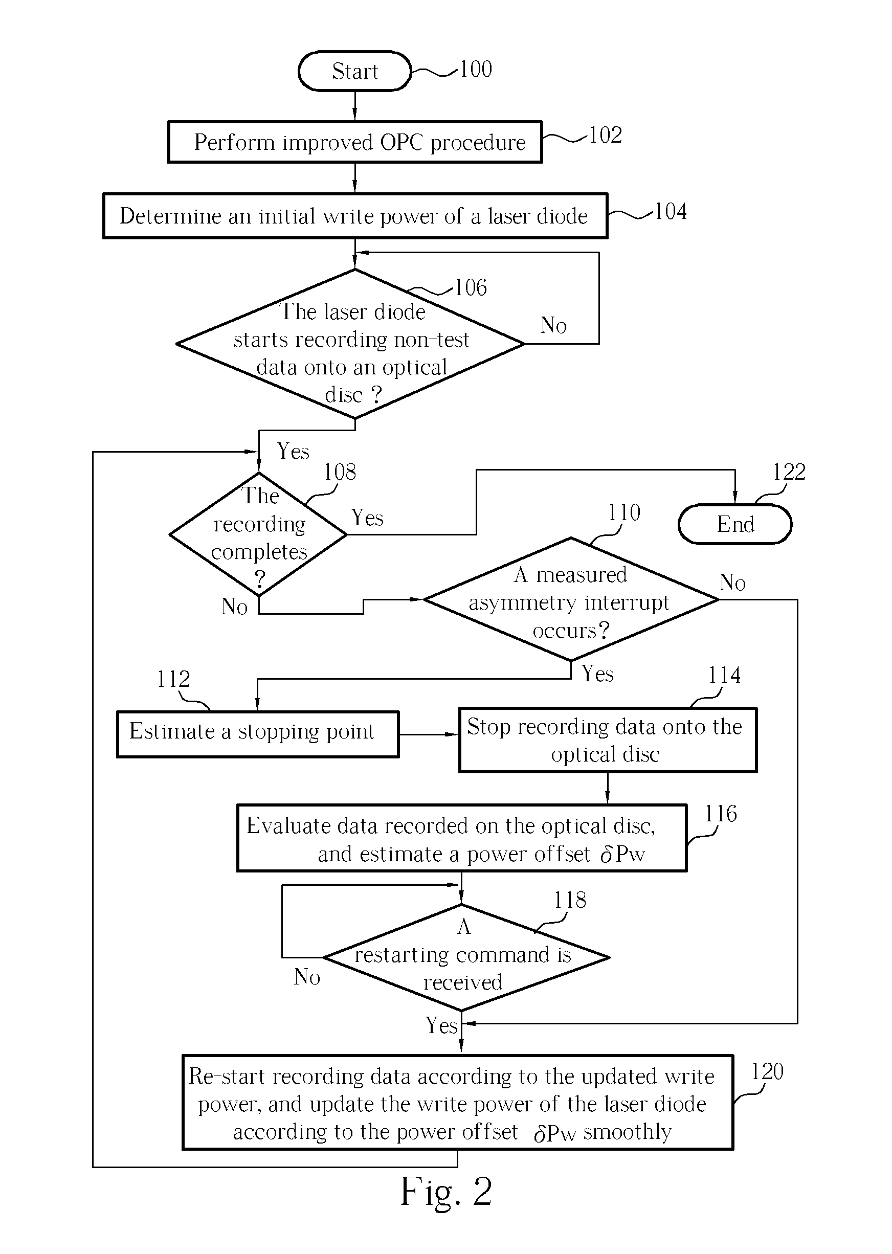
[0021] Please refer to FIG. 2. FIG. 2 is a flow chart of the laser power controlling method according to an embodiment of the present invention. The laser power controlling method is applied to an optical disc recorder, such as a DVD recorder, for controlling a laser diode of the optical disc recorder. The details of this embodiment are shown as follows.

[0022] Step 100: Start.

[0023] Step 102: Perform improved Optimum Power Calibration (OPC) procedure.

[0024] Step 104: Determine an initial write power of a laser diode according to the result of the OPC procedure.

[0025] Step 106: If the laser diode starts recording non-test data (i.e., the actual data) onto an optical disc, proceed to step 108; otherwise, repeat step 106.

[0026] Step 108: If the recording completes, proceed to step 122; otherwise, proceed to step 110.

[0027] Step 110: If a measured asymmetry interrupt occurs, proceed to step 112; otherwise, proceed to step 120.

[0028] Step 112: Estimate a stopping point prior the e...


PUM

PropertyMeasurementUnit
poweraaaaaaaaaa
write poweraaaaaaaaaa
overdrive lengthaaaaaaaaaa

Abstract

A laser power controlling method for controlling power outputted from a laser to record data onto an optical disc and a related apparatus are disclosed. The laser power controlling method includes writing data onto the optical disc according to a characteristic of a write power of the laser, halting writing the data at a stopping point, evaluating the data recorded on the optical disc for generating a first evaluating result, adjusting the characteristic of the write power according to the first evaluating result, and utilizing the laser to restart writing data onto the optical disc from a starting point according to an adjusted characteristic of the write power, wherein there is a gap between the starting point and the stopping point.

Description

BACKGROUND [0001] The present invention relates to a laser controlling method and a related apparatus, and more particularly, to a laser power controlling method and apparatus capable of stopping recording of data for adjusting the laser power and restarting recording of data. [0002] A related art compact disc recorder has a pick-up head, which emits a laser beam to heat the recording layer of a compact disc for storing data in a digital format. Base on the well-known disc specification, a pit on the compact disc is defined to represent “0”, and a land of the compact disc is defined to represent “1”. Unfortunately, different compact discs have varying energy absorption characteristics of the laser beam due to different properties of the recording layers. For example, when the same laser beam (i.e., the same laser power), illuminates DVD-R discs taken from different manufacturers, different levels of etching occur. As a result, when a compact disc is manufactured, a desired write pow...

Claims


Application Information

Patent Timeline
Patent Type & Authority Applications(United States)
IPC IPC(8): G11B7/12G11B7/125
CPCG11B7/1263
Inventor CHANG, KUANG-JUNGMA, PAO-PING
Owner MEDIATEK INC
Why Eureka
Try Eureka