Hole saw with waste plug ejector

a waste plug and hole saw technology, applied in the field of hole saws, to achieve the effect of convenient use, low manufacturing cost and convenient us

Inactive Publication Date: 2011-06-28
EISERER CECIL +1
View PDF27 Cites 42 Cited by
  • Summary
  • Abstract
  • Description
  • Claims
  • Application Information

AI Technical Summary

Problems solved by technology

If the plug remains stuck in the saw, the operator may loosen the main set screw, rotationally disengaging the saw from the drill bit.

Method used


Image

  • Hole saw with waste plug ejector
  • Hole saw with waste plug ejector
  • Hole saw with waste plug ejector

Examples


Embodiment Construction

[0016]As required, detailed embodiments of the present invention are disclosed herein; however, it is to be understood that the disclosed embodiments are merely exemplary of the invention, which may be embodied in various forms. Therefore, specific structural and functional details disclosed herein are not to be interpreted as limiting, but merely as a basis for the claims and as a representative basis for teaching one skilled in the art to variously employ the present invention in virtually any appropriately detailed structure. It is also noted that any reference to the words top, bottom, up and down, and the like, in this application refers to the alignment shown in the various drawings, as well as the normal connotations applied to such devices, and is not intended to restrict positioning of structures of the application in actual use.

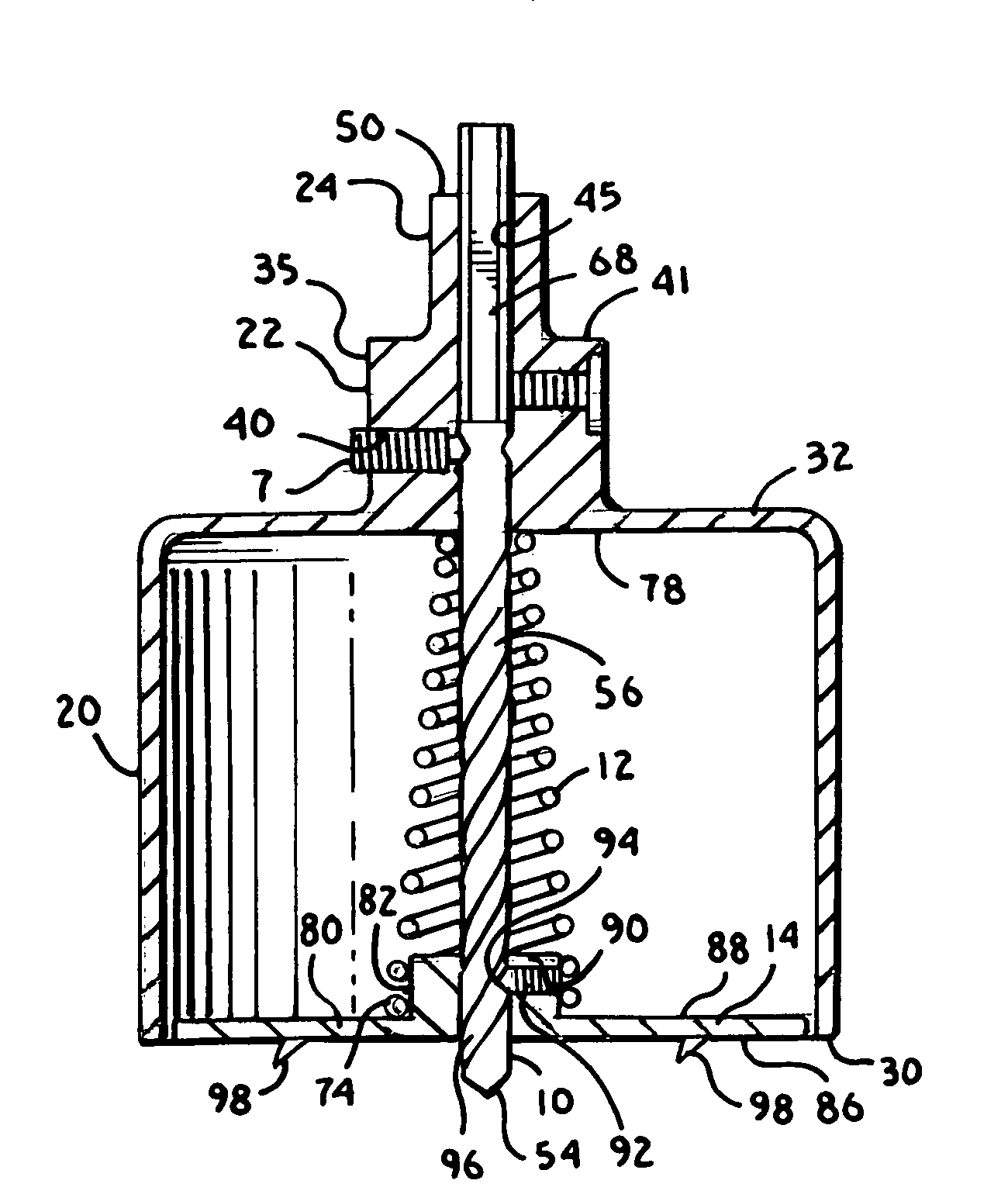
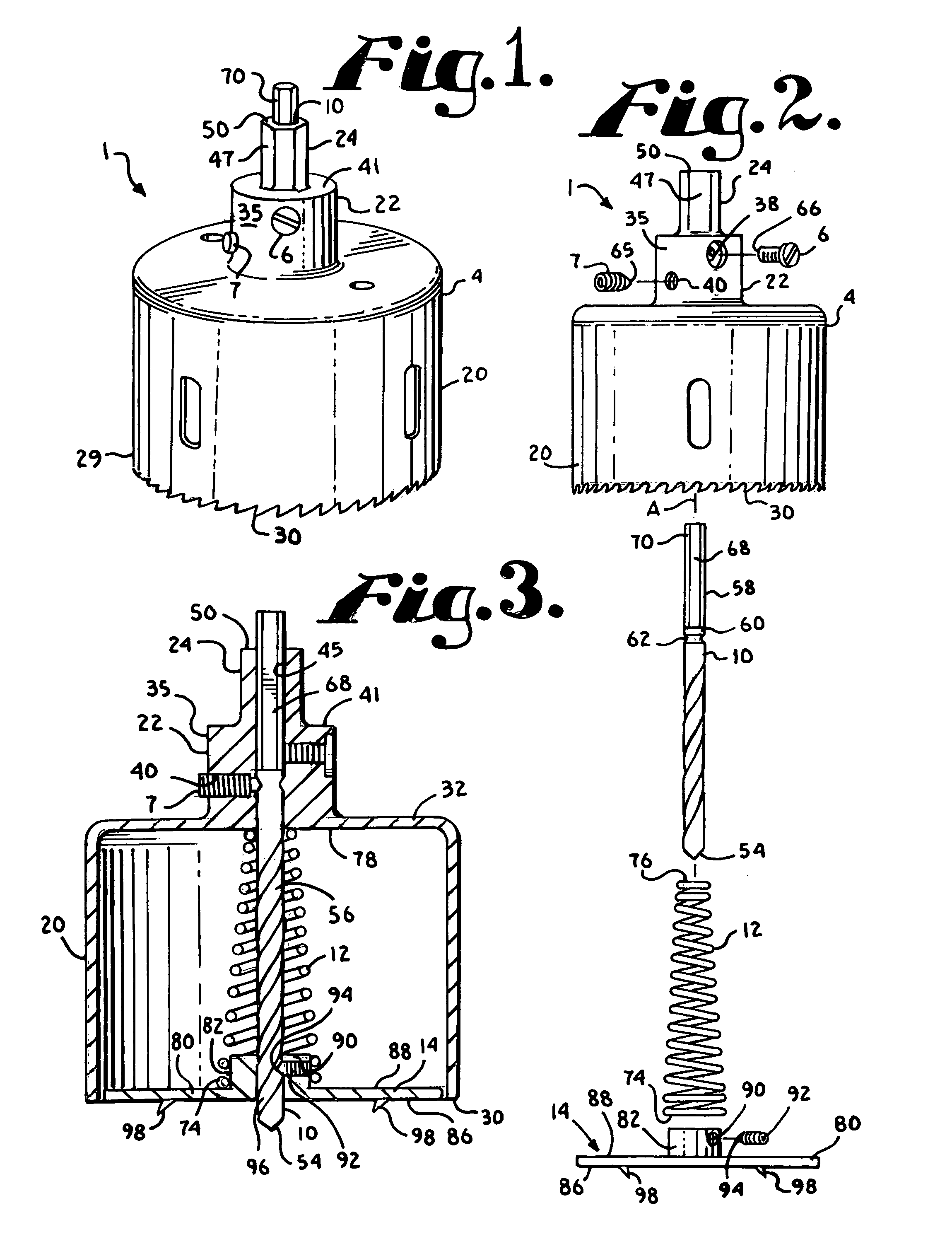
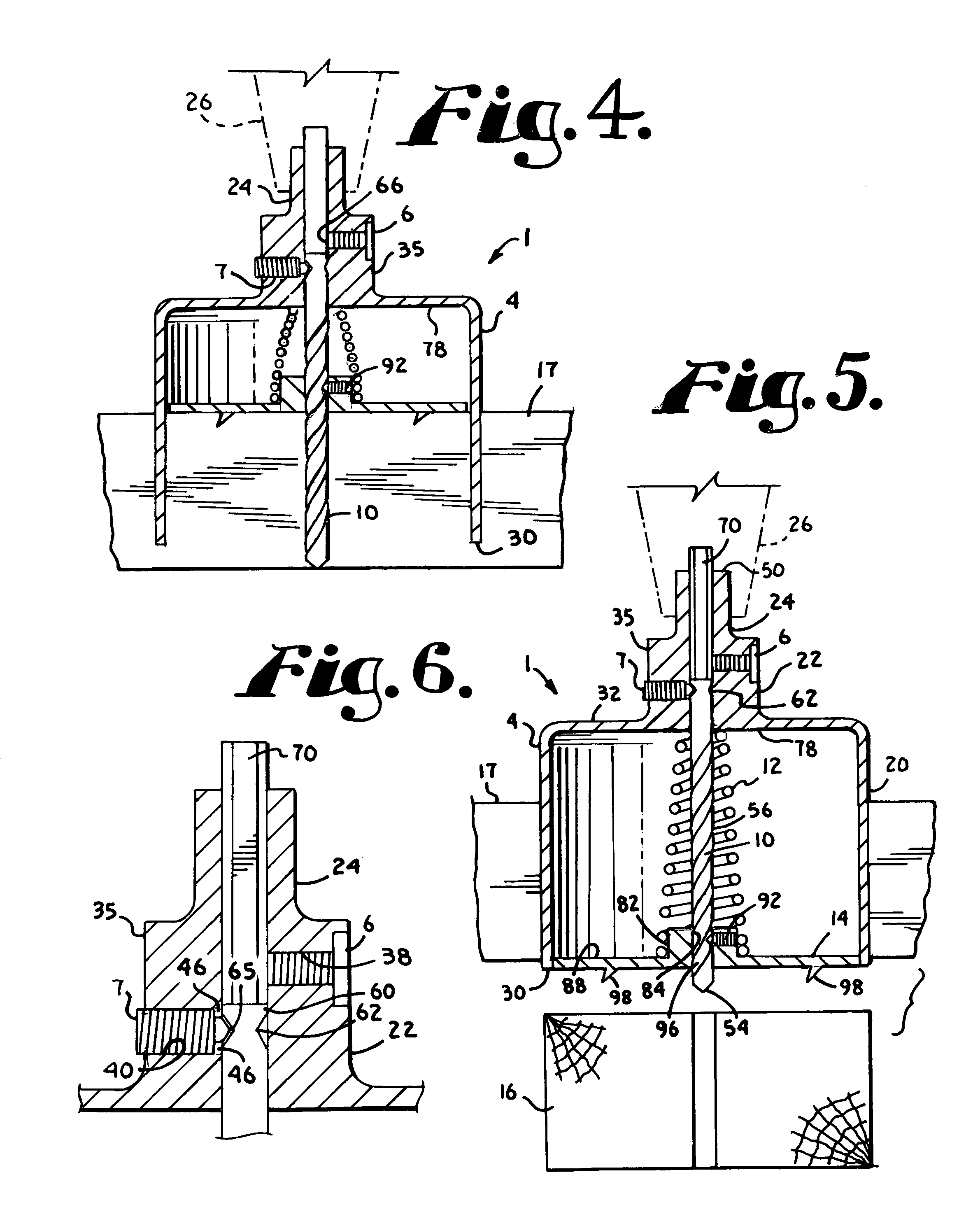
[0017]With reference to FIGS. 1-5, the reference numeral 1 generally designates a hole saw according to the invention including a housing 4 with co...


PUM

PropertyMeasurementUnit
detailed structureaaaaaaaaaa
diameteraaaaaaaaaa
outer diameteraaaaaaaaaa

Abstract

A hole saw having a tubular cutting portion, a pilot drill bit, an ejection plate disposed within the tubular cutting portion and a compression spring cooperating with the plate further includes a guide structure fixed to the ejection plate and slidingly cooperating with a helical flute of the pilot drill bit. The compression spring and cooperating guide structure provide a combination of linear and rotational ejection of a waste plug from the hole saw. A duel set screw feature facilitates waste plug removal if needed and includes a first set screw frictionally engaged with a flat surface of the drill bit and a second set screw cooperating with a circular groove running about the drill bit.

Description

BACKGROUND OF THE INVENTION[0001]The present invention is directed to hole saws that have a waste plug or slug removal apparatus.[0002]Hole saws are useful for cutting circular holes in a variety of materials, including, but not limited to wood, metal, plastics and dry wall. Hole saws are typically in the form of a hollow cylinder or tube having a circular edge with cutting teeth at one end and structure for attachment to a power drill or other type of drilling machine at the other end thereof. Typically, hole saws are sized and shaped to cooperate with the bit of a drill such that the cutting edge and possibly a portion of the flute of the bit extend in a direction forward of the circular cutting teeth of the saw to provide a center guide or pilot for placement of the hole in a desired location on a piece of material. In the art, the term “drill” may be used to describe a drilling machine or a drill bit for use in a drilling machine. Therefore, in this application, for the sake of ...

Claims


Application Information

Patent Timeline
Patent Type & Authority Patents(United States)
IPC IPC(8): B23B51/04
CPCB23B51/0453Y10T408/895Y10T408/51
Inventor EISERER, CECILBRUNSCHER, DAVID
Owner EISERER CECIL
Why Eureka
Try Eureka