Switch device

a technology of switch and switch plate, which is applied in the direction of permanent magnets, magnetic/electric field switches, magnetic bodies, etc., can solve the problems of steep change, achieve the effect of improving switching performance, reducing armature and yoke sliding, and reducing the sliding of the yok

Inactive Publication Date: 2011-07-12
TOKIN CORP +1
View PDF7 Cites 2 Cited by
  • Summary
  • Abstract
  • Description
  • Claims
  • Application Information

AI Technical Summary

Benefits of technology

[0004]The invention has been devised in view of the above-described circumstances, and its object is to provide a switch device which can be realized with a structure which allows the fixed contact and the movable contact to be moved into contact with or away from each other while preventing the ingress of foreign objects such as lubricating oil into the case accommodating the fixed contact and the movable contact, which is capable of effecting more speedily the movement of the both contacts into contact with or away from each other to improve the switching performance, and which is capable of minimizing the sliding contact of related parts producing wear dust harmful to the contact between the fixed contact and the movable contact.
[0006]According to the above-described aspect of the invention, the movable contact positioned in the sealed case can be moved together with the movable contact spring with respect to the fixed contact by the movement of the magnetic shunt body which moves outside the sealed case. Hence, the movement of the movable contact and the fixed contact, which are accommodated in the sealed case, into contact with and away from each other can be effected without the ingress into the interior of the sealed case of foreign objects including lubricating oil and inorganic and organic substances which are present in the vicinities of the sealed case. Thus, it is possible to eliminate the possibility of causing the conventional problem of faulty conduction between the contacts due to the entrants.
[0007]In addition, the movement of the movable contact (movement into contact with or away from the fixed contact) due to the movement of the magnetic shunt body is based on the change of the magnetically attracting force of the magnet with respect to the armature through the pair of yokes, and its change is steep. Hence, the movement of the movable contact and the fixed contact into contact with and away from each other can be effected more speedily, thereby making it possible to improve the switching performance.
[0008]In addition, since the configuration provided is such that the movable contact spring is provided with a bent portion which is bent in spaced-apart relation to the armature, the bent portion being provided between a fulcrum portion at a time when the movable contact spring moves with respect to the fixed contact and a portion where the armature is provided, it is possible to alleviate the sliding of the armature and the yoke. This makes it possible to minimize the production of wear dust which is harmful to the contact between the fixed contact and the movable contact.

Problems solved by technology

In addition, the movement of the movable contact (movement into contact with or away from the fixed contact) due to the movement of the magnetic shunt body is based on the change of the magnetically attracting force of the magnet with respect to the armature through the pair of yokes, and its change is steep.

Method used


Image

  • Switch device
  • Switch device
  • Switch device

Examples


Embodiment Construction

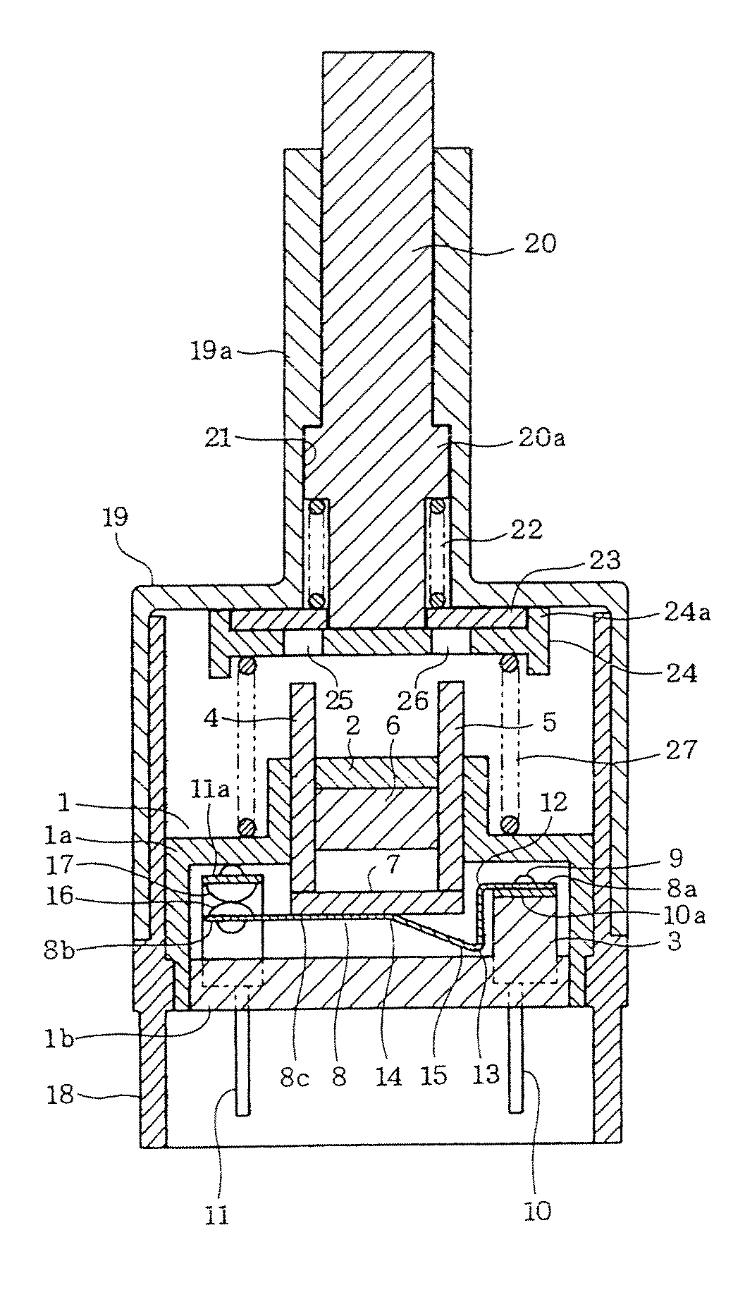
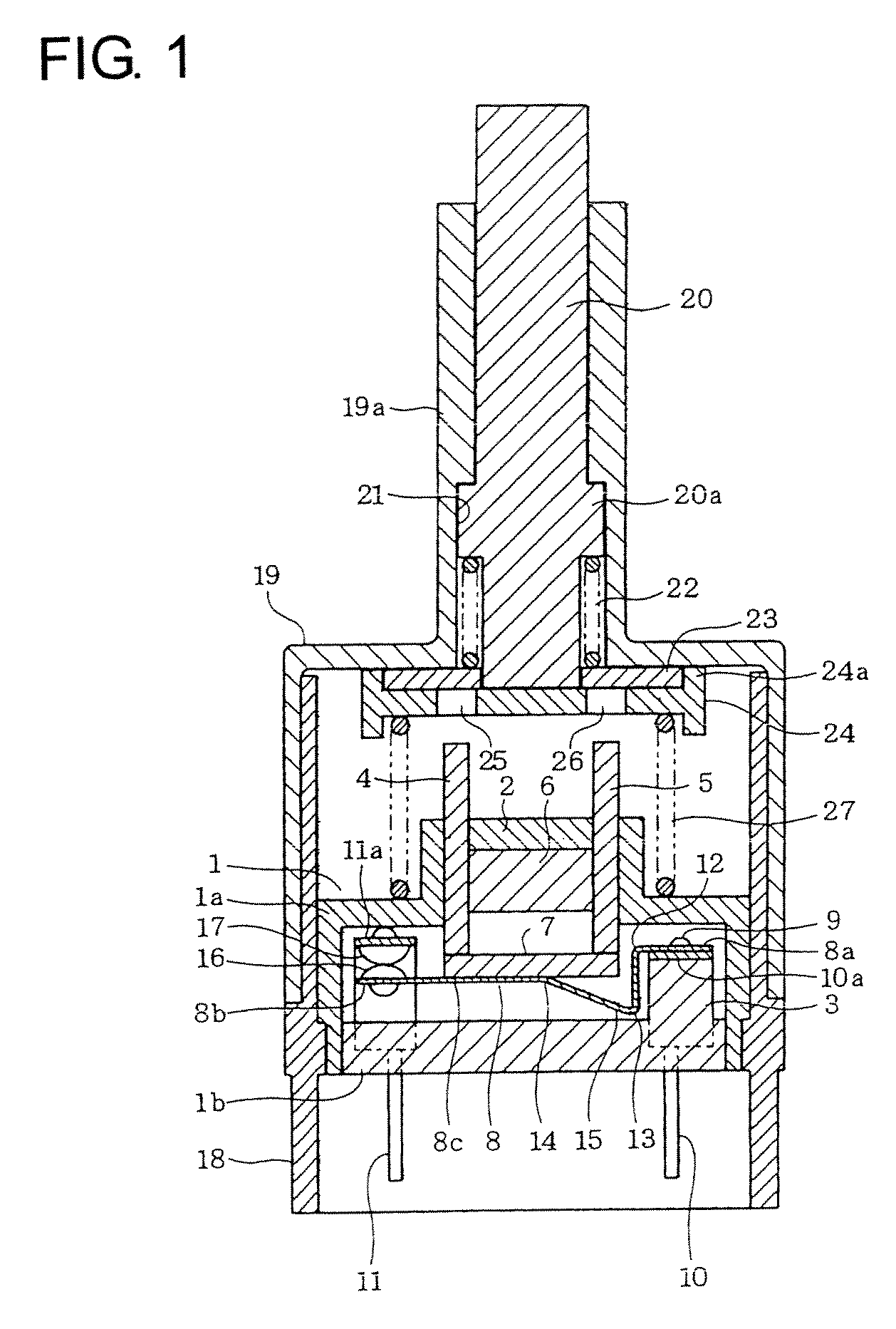
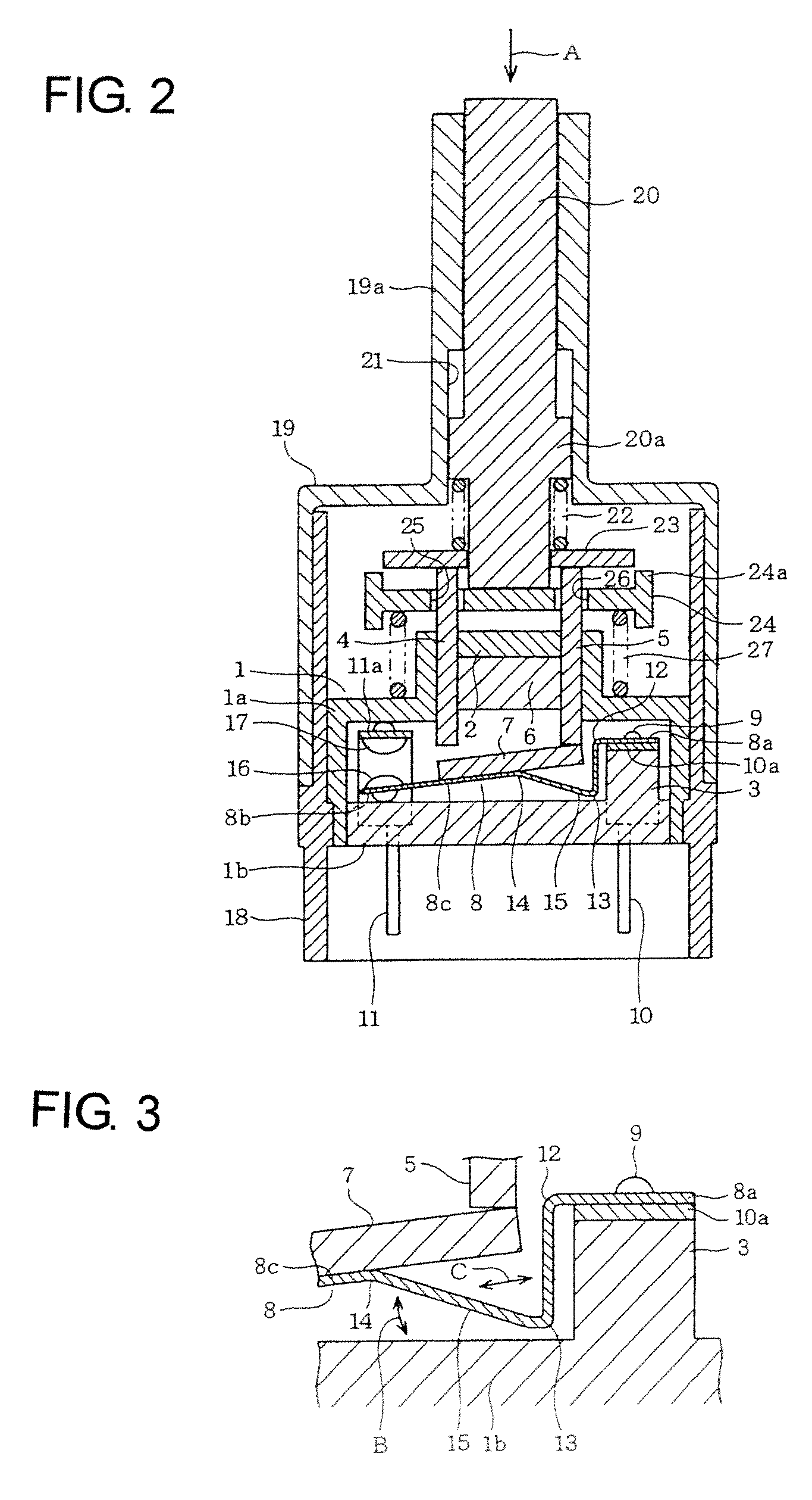
[0015]Hereafter, by applying the invention to a stop lamp switch for a vehicle, a description will be given of its first embodiment with reference to FIGS. 1 to 3.

[0016]First, FIG. 1 shows an overall configuration of the stop lamp switch for a vehicle, and a sealed case 1 is its main body. This sealed case 1 is comprised of a case main body portion 1a and a case base portion 1b, and the case main body portion 1a of these has a cap shape in which an upper surface portion is closed by having a protruding portion 2 in its central portion and a bottom is open. The case base portion 1b has a flat shape except that a projecting portion 3 is provided on an upper surface of a right-hand portion in the drawing.

[0017]A pair of yokes 4 and 5 are provided in such a manner as to be passed through the protruding portion 2 of the aforementioned case main body portion 1a. These yokes 4 and 5 are both formed of a magnetic material such as iron. As these yokes 4 and 5 are provided by being inserted d...


PUM


Abstract

A movable contact positioned in a sealed case is moved together with a movable contact spring provided with an armature by a magnetic shunt body which is moved outside the sealed case. The movement of the movable contact (movement of the movable contact spring) due to the movement of the magnetic shunt body is based on the change of the magnetically attracting force of a magnet with respect to the armature through a pair of yokes. The movable contact spring is provided with a bent portion which is bent in spaced-apart relation to the armature, the bent portion being provided between a fulcrum portion at a time when the movable contact spring moves and a portion where the armature is provided.

Description

BACKGROUND OF THE INVENTION[0001]The present invention relates to a switch device in which an operating structure of a contact is improved.[0002]Generally, a switch device is generally used in which a rod-like moving element is provided by being passed through a case in which a fixed contact, a movable contact, and a spring for normally bringing the movable contact into contact with or moving it away from the fixed contact are accommodated, and as the moving element is movably operated, the movable contact is moved relative to the fixed contact so as to be moved away from or into contact with the fixed contact (e.g., refer to JP-A-2005-235632).[0003]The switch device having the above-described configuration is used as, for instance, a stop lamp switch for a vehicle, and lubricating oil applied to various mechanical portions and inorganic or organic substances contained in the product are present in the vicinities of that stop lamp switch for a vehicle. Meanwhile, with the above-desc...

Claims


Application Information

Patent Timeline
Patent Type & Authority Patents(United States)
IPC IPC(8): H01H9/00
CPCH01H36/008H01H1/26H01H36/0046
Inventor YAMADA, TOMIOIDE, TATSUMIOTA, YOSHINORI
Owner TOKIN CORP
Why Eureka
Try Eureka