Thermal stir welding apparatus

a technology of stir welding and welding apparatus, which is applied in the direction of welding/cutting auxillary devices, non-electric welding devices, auxillary welding devices, etc., and can solve problems such as possible recrystallization of grinding/extrusion elements

Inactive Publication Date: 2011-07-19
NASA
View PDF21 Cites 8 Cited by
  • Summary
  • Abstract
  • Description
  • Claims
  • Application Information

AI Technical Summary

Benefits of technology

[0022]A further advantage of the present invention is that the invention can provide long longitudinal welds of varying material thickness.
[0023]Yet another advantage of the present invention is that the invention can be used to form longitudinal welds exhibiting a so

Problems solved by technology

Subsequently, a separate grinding/extrusion element recrystallizes possible, undesirable dend

Method used


Image

  • Thermal stir welding apparatus
  • Thermal stir welding apparatus

Examples


Embodiment Construction

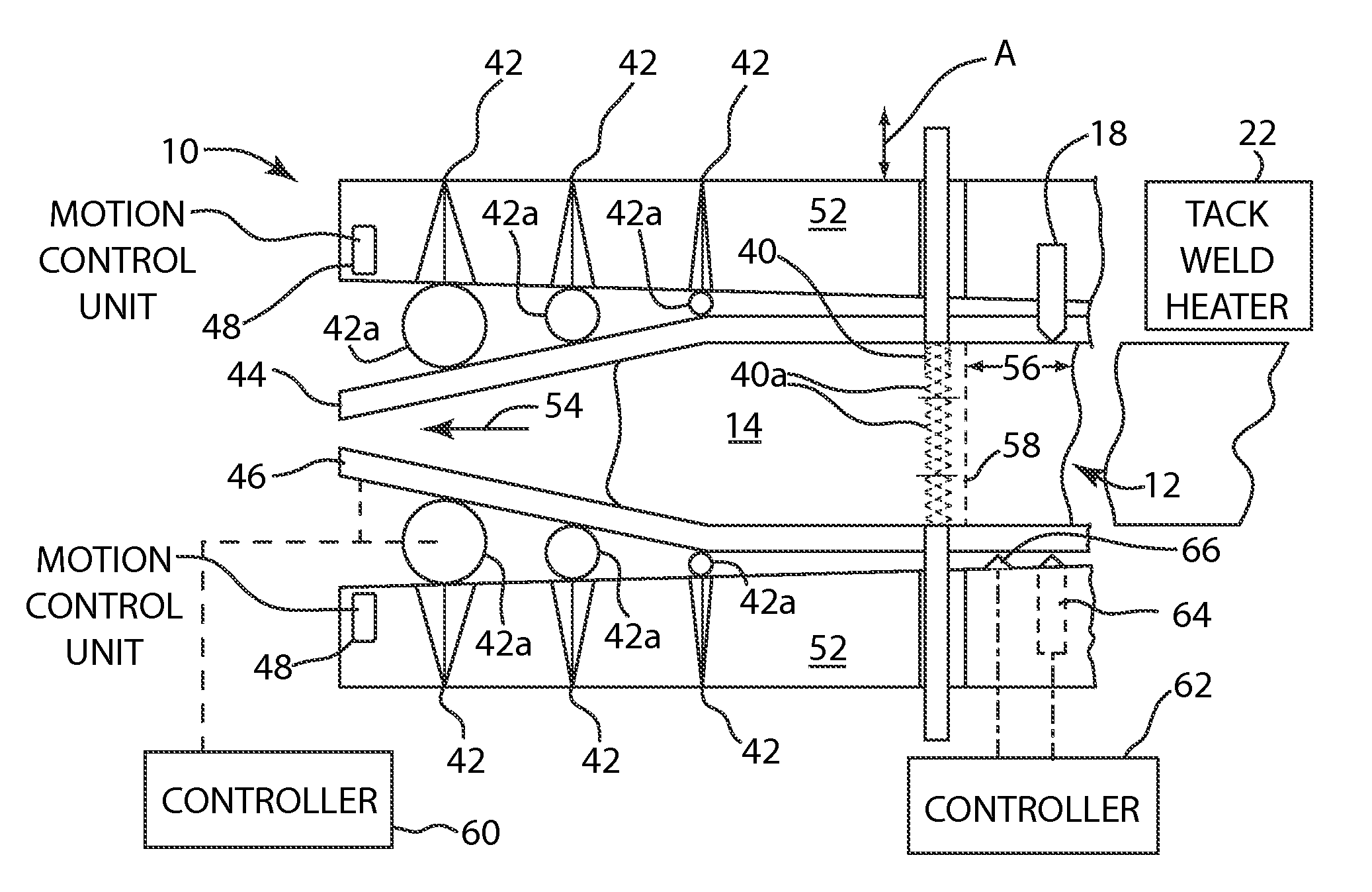
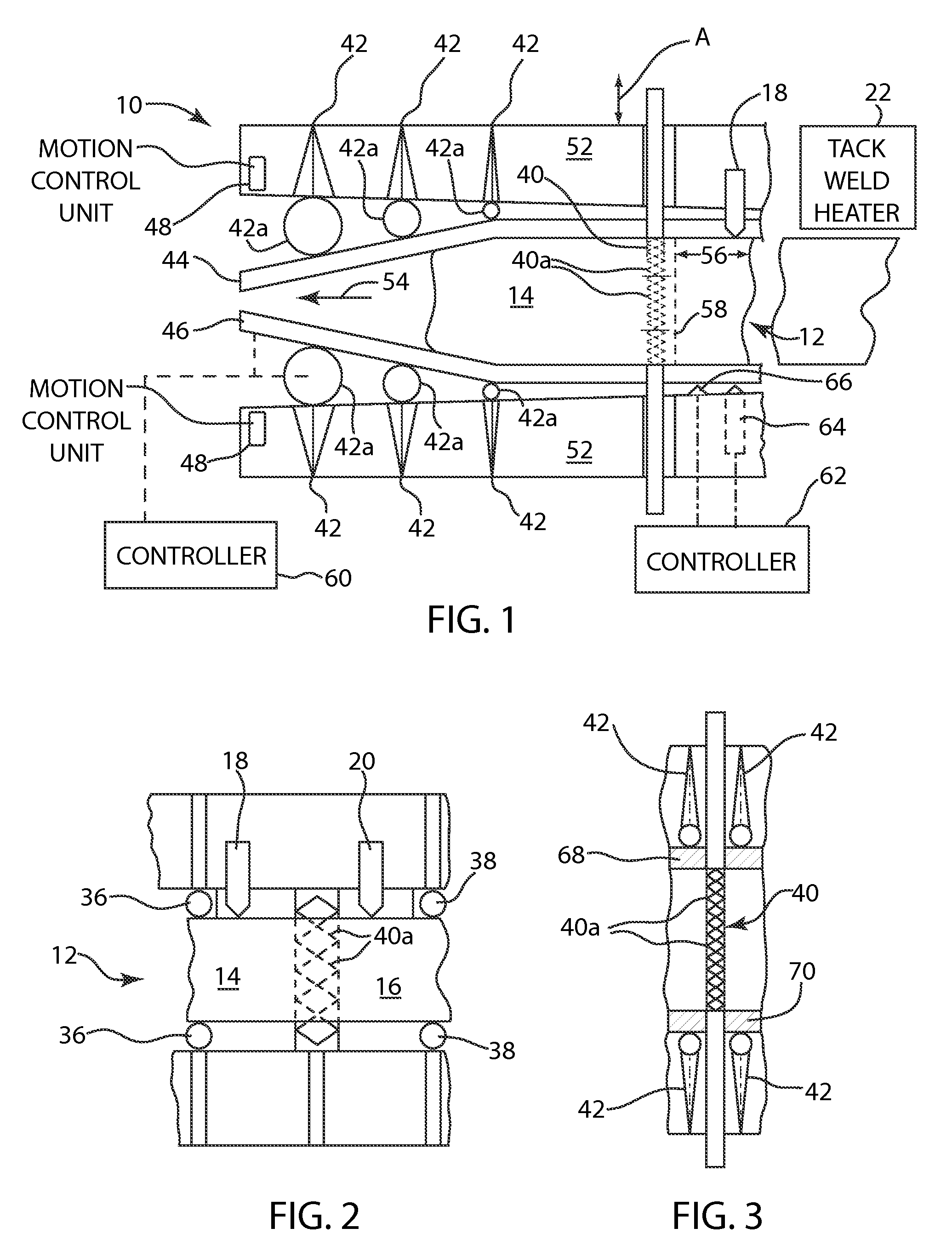
[0028]Referring now to FIG. 1 and FIG. 2, there is shown a welding device, generally denoted 10, which is adapted to join together first and second elements 14 and 16 of a workpiece 12. The welding device 10 includes heating elements 18 and 20.

[0029]Heating element 18 provides sufficient heat to plasticize or melt the material of element 14 and may comprise such conventional heating devices as lasers or plasma torches or other suitable devices known in the art. Similarly, heating element 20 provides sufficient heat to plasticize or melt the material of element 16. As a result, together, heating elements 18 and 20 transform a portion of the solid material of the workpiece 12, viz., respective abutting portions of elements 14, 16 to form an interface 34 (see FIG. 2) in a plasticized or melted phase, between the elements 14, 16.

[0030]The heating elements 18 and 20 can be controlled individually for providing heating at a desired separate temperature. For example, where elements 14 and ...


PUM

PropertyMeasurementUnit
Temperatureaaaaaaaaaa
Lengthaaaaaaaaaa
Forceaaaaaaaaaa

Abstract

A welding method and apparatus are provided for forming a weld joint between first and second elements of a workpiece. The method includes heating the first and second elements to form an interface of material in a plasticized or melted state interface between the elements. The interface material is then allowed to cool to a plasticized state if previously in a melted state. The interface material, while in the plasticized state, is then mixed, for example, using a grinding/extruding process, to remove any dendritic-type weld microstructures introduced into the interface material during the heating process.

Description

CROSS REFERENCE TO RELATED APPLICATION[0001]This application is a division of application Ser. No. 09 / 994,506 filed on Nov. 27, 2001 now abandoned.ORIGIN OF THE INVENTION[0002]This invention was made by employees of the United States Government and may be manufactured and used by or for the Government for governmental purposes without the payment of any royalties.BACKGROUND OF THE INVENTION[0003]1. Field of the Invention[0004]The present invention relates to a welding method and apparatus, and in particular, to a welding method and apparatus which separately plasticizes or melts the surfaces to be joined followed by a subsequent weld matrix mixing process.[0005]2. Background of the Invention[0006]Welding processes can be classified into one of two categories, fusion welding and solid state welding. Fusion welding involves melting material to be welded and includes such processes as MIG, TIG and VPPA welding. Solid state welding joins materials without a melting step and include the ...

Claims


Application Information

Patent Timeline
IPC IPC(8): B23K31/02B23K20/00
CPCB23K20/001B23K2203/10Y10T29/5116B23K2203/18B23K2203/22B23K2203/12B23K2103/05B23K2103/10B23K2103/12B23K2103/14B23K2103/18B23K2103/22B23K2103/24
Inventor DING, R. JEFFREY
Owner NASA
Why Eureka
Try Eureka