
Autonomic control of calibration for pointing device

a technology of pointing device and autonomic control, which is applied in the field of computer systems, can solve the problems of many users not having the sophistication to select an optimal rate, many problems associated with this trial and error process, and many users not having the sophistication to achieve optimal rate selection

Active Publication Date: 2011-07-26
GOOGLE LLC
View PDF8 Cites 2 Cited by
  • Summary
  • Abstract
  • Description
  • Claims
  • Application Information

AI Technical Summary

Benefits of technology

The invention provides a method and system for automatically selecting an optimal rate of movement of a cursor on a computer screen. It uses a calibration module to modify the rate of movement of the cursor based on the user's pointing device events. The event detection module detects indicators of a less-than-optimal calibration and modifies the rate of movement of the cursor accordingly. The application interface module communicates with the application being performed on the computer. The invention also includes a storage module for storing calibration information and a method for autonomously modifying the rate of movement of the cursor based on the detected indicators. The technical effects of the invention include improved efficiency and accuracy in selecting the optimal rate of movement of the cursor, which can enhance the user's experience and productivity.

Problems solved by technology

There are, however, many issues associated with this trial and error process.
Many users do not have the sophistication to operate the pointing device interface module, and even if they did, may not have the sophistication to select an optimal rate.
However, conventional pointing device interface modules are not capable of easily reacting to these changes.

Method used


Image

  • Autonomic control of calibration for pointing device
  • Autonomic control of calibration for pointing device
  • Autonomic control of calibration for pointing device

Examples


Embodiment Construction

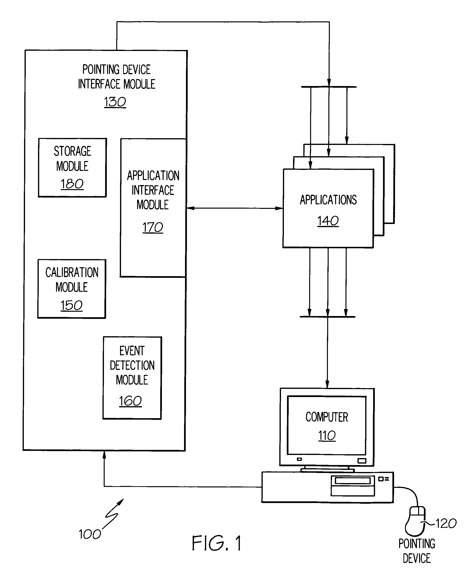
[0018]FIG. 1 illustrates a computer system 100 including a computer 110, a pointing device 120, a pointing device interface module 130, and one or more applications 140 executed on the computer 110. The pointing device 120 generates pointing device events, which are received by the pointing device interface module 130. These pointing device events may be transmitted directly to the applications 140 or, in certain aspects of the computer system 100, transmitted to the applications 140 via the pointing device interface module 130. The pointing device interface module 130 may also include a calibration module 150, an event detection module 160, an application interface module 170, and a calibration information storage module 180.

[0019]The pointing device 120 facilitates selecting user interface elements and inputting spatial data into the computer 110. The pointing device 120 may generate pointing device events, which are received by the pointing device interface module 130. A pointing...


PUM


Abstract

A computer system includes a computer, a calibration module, an event detection module, and an application interface module. The computer executes one or more applications and receives pointing device events generated by a pointing device connected to the computer. The calibration module modifies a rate of movement of a cursor displayed by the computer in response to the pointing device events. The event detection module detects a less-than-optimal calibration indicator from the pointing device events and modifies the rate of movement of the cursor. The application interface module communicates with the application being performed on the computer. A storage module for storing calibration information may also be included.

Description

BACKGROUND OF THE INVENTION[0001]1. Field of the Invention[0002]The disclosure relates generally to computer systems and, more specifically, to a method and system for controlling the calibration of movements associated with pointing device events.[0003]2. Description of the Related Art[0004]Computer systems have become increasingly interactive with computer users. The advent of the personal computer provided a dedicated computer, keyboard, and a display device, such as a monitor, to nearly every computer user. Further developments in operating systems such as graphical user interfaces and multimedia support have resulted in a highly interactive experience for computer users. Pointing devices such as mice, light pens, digitizing tablets, trackballs, touch pads, and touch screens have provided the user with additional control and interactivity. In the future, data gloves and gesture recognition are expected to further improve the ability of the user to point to objects or commands th...

Claims


Application Information

Patent Timeline
Patent Type & Authority Patents(United States)
IPC IPC(8): G06F3/033G09G5/08G06F3/038G06F3/041
CPCG06F3/038G06F3/0418
Inventor MASSELLE, ERIC L.PAGAN, WILLIAM G
Owner GOOGLE LLC
Learn More