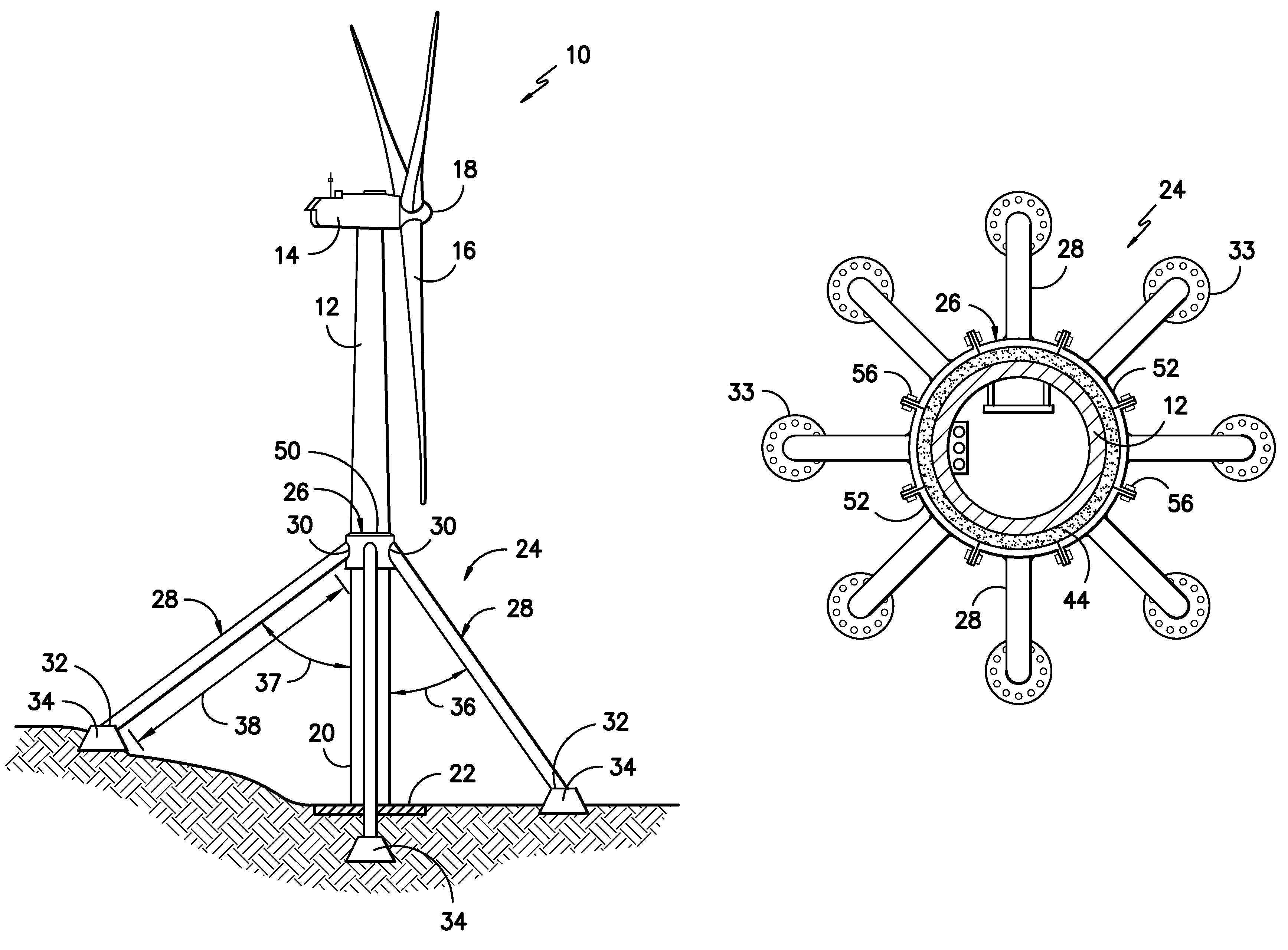
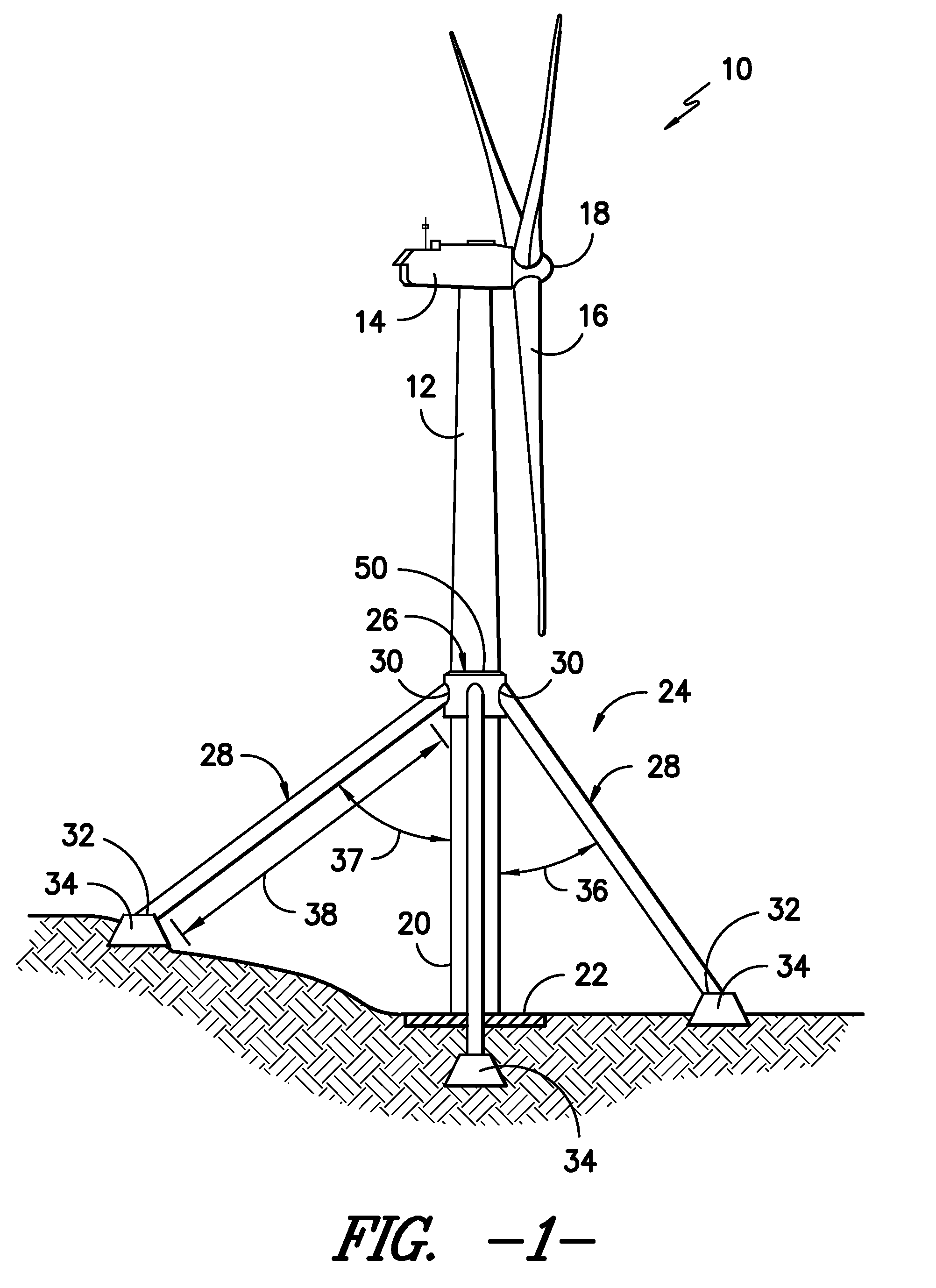
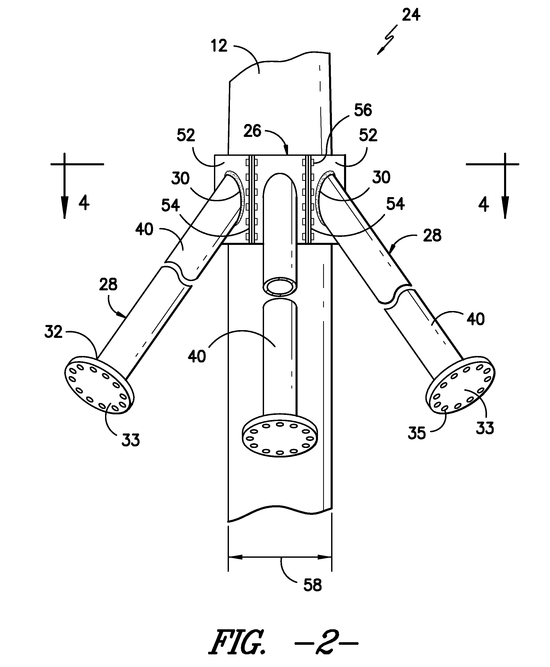
Onshore wind turbine with tower support system

a technology for wind turbines and support systems, which is applied in the field of wind turbines, can solve the problems of limiting factors such as the dimensions of the lower tower sections, the increase in the cost of manufacture, transportation and erecting of the tower structure, and the inability to meet the requirements of the customer, so as to reduce the weight and diameter of the lower section

Active Publication Date: 2011-08-09
GENERAL ELECTRIC CO
View PDF34 Cites 52 Cited by
  • Summary
  • Abstract
  • Description
  • Claims
  • Application Information

AI Technical Summary

Benefits of technology

[0006]In accordance with aspects of the invention, a wind turbine is provided with a nacelle mounted atop a tower. The nacelle is configured with any manner of wind turbine power generating components. The tower has a base end that is configured for support on any manner of suitable ground level foundation. A support system is provided for the tower that allows for reduction in the weight and diameter of the lower sections of the tower. The support system includes an axially extending circumferential sleeve mounted around the tower at a pre-defined location between the base end and the nacelle, for example between about 25% to about 75% of the tower height measured from the base. A plurality of support legs have a first end rigidly affixed to the sleeve and an opposite foot end configured for mounting to any manner of suitable ground level footing. The support legs have a length and extension angle relative to a vertical axis of the tower so as to provide vertical and lateral support around the circumference of the tower.
[0010]The support system provides for a reduction in the weight and footprint of the base sections of the tower. In this regard, the tower may be a tubular member that has a substantially constant diameter from the sleeve location to the base end, and may also have a substantially constant mass per unit of length from the sleeve to the base end.

Problems solved by technology

The tower structures of these large wind turbines can be massive, particularly at the base section of the tower wherein a significant footprint and weight are needed to achieve design tower support criteria.
In this regard, the towers are becoming increasing more expensive to manufacture, transport, and erect.
In many instances, the dimensions of the lower tower sections are limiting factors in site selection and transport of the tower sections to the site.

Method used


Image

  • Onshore wind turbine with tower support system
  • Onshore wind turbine with tower support system
  • Onshore wind turbine with tower support system

Examples


Embodiment Construction

[0021]Reference now will be made in detail to embodiments of the invention, one or more examples of which are illustrated in the drawings. Each example is provided by way of explanation of the invention, not limitation of the invention. In fact, it will be apparent to those skilled in the art that various modifications and variations can be made in the present invention without departing from the scope or spirit of the invention. For instance, features illustrated or described as part of one embodiment can be used with another embodiment to yield a still further embodiment. Thus, it is intended that the present invention include such modifications and variations as come within the scope of the appended claims and their equivalents.

[0022]FIG. 1 illustrates a wind turbine 10 of conventional construction. The wind turbine 10 includes a tower 12 with a nacelle 14 mounted thereon. A plurality of turbine blades 16 are mounted to a rotor hub 18, which is in turn connected to a main flange ...


PUM


Abstract

A wind turbine includes a nacelle with any manner of associated power generation equipment. The nacelle is mounted atop a tower having a base end configured for support on a ground level foundation. A tower support system provides support to the tower and includes an axially extending circumferential sleeve mounted around the tower at a location between the base end and the nacelle. A plurality of support legs are disposed around the sleeve, with each support leg having a first end rigidly affixed to the sleeve and an opposite foot end configured for mounting to a ground level footing. The support legs extend from the sleeve with a length and at an acute extension angle relative to a longitudinal axis of the tower so as to provide a designed degree of vertical and lateral support around the circumference of the tower.

Description

FIELD OF THE INVENTION[0001]The present invention relates generally to the field of wind turbines, and more particularly to a base support system for onshore wind turbine towers.BACKGROUND OF THE INVENTION[0002]Modern land-based (“onshore”) wind turbines in the megawatt range have grown increasingly more powerful and correspondingly larger. The towers that support the power generating components of these wind turbines can exceed well over 60 meters in height. For example, GE Wind Energy offers a 2.5 MW wind turbine with standard available hub heights of 75 meters, 85 meters, and 100 meters. Larger wind turbines with hub heights in excess of 100 meters are becoming more common.[0003]The tower structures of these large wind turbines can be massive, particularly at the base section of the tower wherein a significant footprint and weight are needed to achieve design tower support criteria. In this regard, the towers are becoming increasing more expensive to manufacture, transport, and e...

Claims


Application Information

Patent Timeline
Patent Type & Authority Patents(United States)
IPC IPC(8): F03D11/04E04H12/20
CPCF03D1/001F03D11/04E04H12/08F05B2240/913Y02E10/728Y10S416/06F03D13/20F03D13/10Y02E10/72
Inventor GEVERS, WILLIAM FRANCIS
Owner GENERAL ELECTRIC CO
Why Eureka
Try Eureka