
Receptacle connector

a technology of receptacles and connectors, applied in the direction of coupling devices, two-part coupling devices, electrical apparatus, etc., can solve the problems of poor electrical signal transmission, the terminals of plugs cannot be contacted well with the receptacle terminals,

Inactive Publication Date: 2011-08-09
CHENG UEI PRECISION IND CO LTD
View PDF6 Cites 3 Cited by
  • Summary
  • Abstract
  • Description
  • Claims
  • Application Information

AI Technical Summary

Benefits of technology

[0007]As described above, the contacting portion is formed by a free end of the bending portion extending along a tangent direction thereof. When the plug connector is inserted into the accommodating chamber of the receptacle connector, pressure can be afforded averagely by the bending portion and the contacting portion, so that an elastic deformation of the terminals can be avoided, and a contact reliability of the terminals and plug terminals is improved, and electrical signals can be transmitted normally.

Problems solved by technology

However, when the receptacle terminals are pressed down by the plug terminals of the plug connector, pressure may be concentrated on the contacting portion so as to result in an elastic permanent deformation, as a result the plug terminals of the plug can't be contacted with the receptacle terminals well and electrical signal transmissions are bad.

Method used


Image

  • Receptacle connector
  • Receptacle connector
  • Receptacle connector

Examples


Embodiment Construction

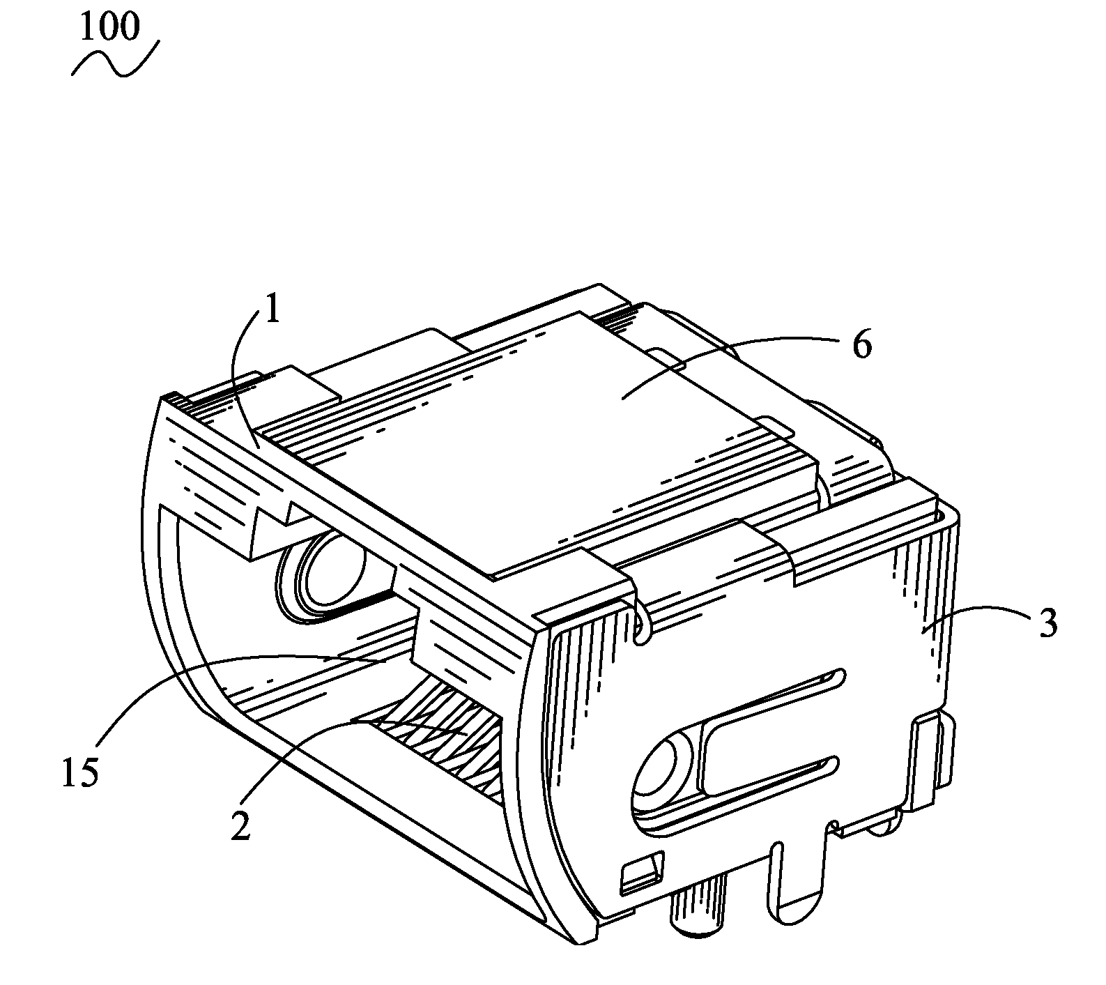
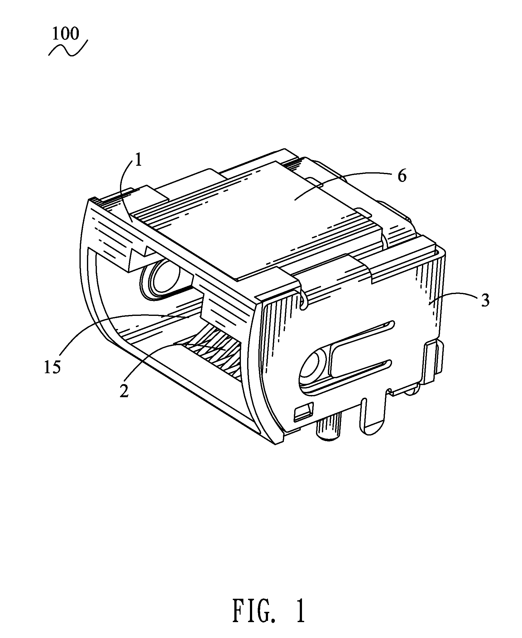
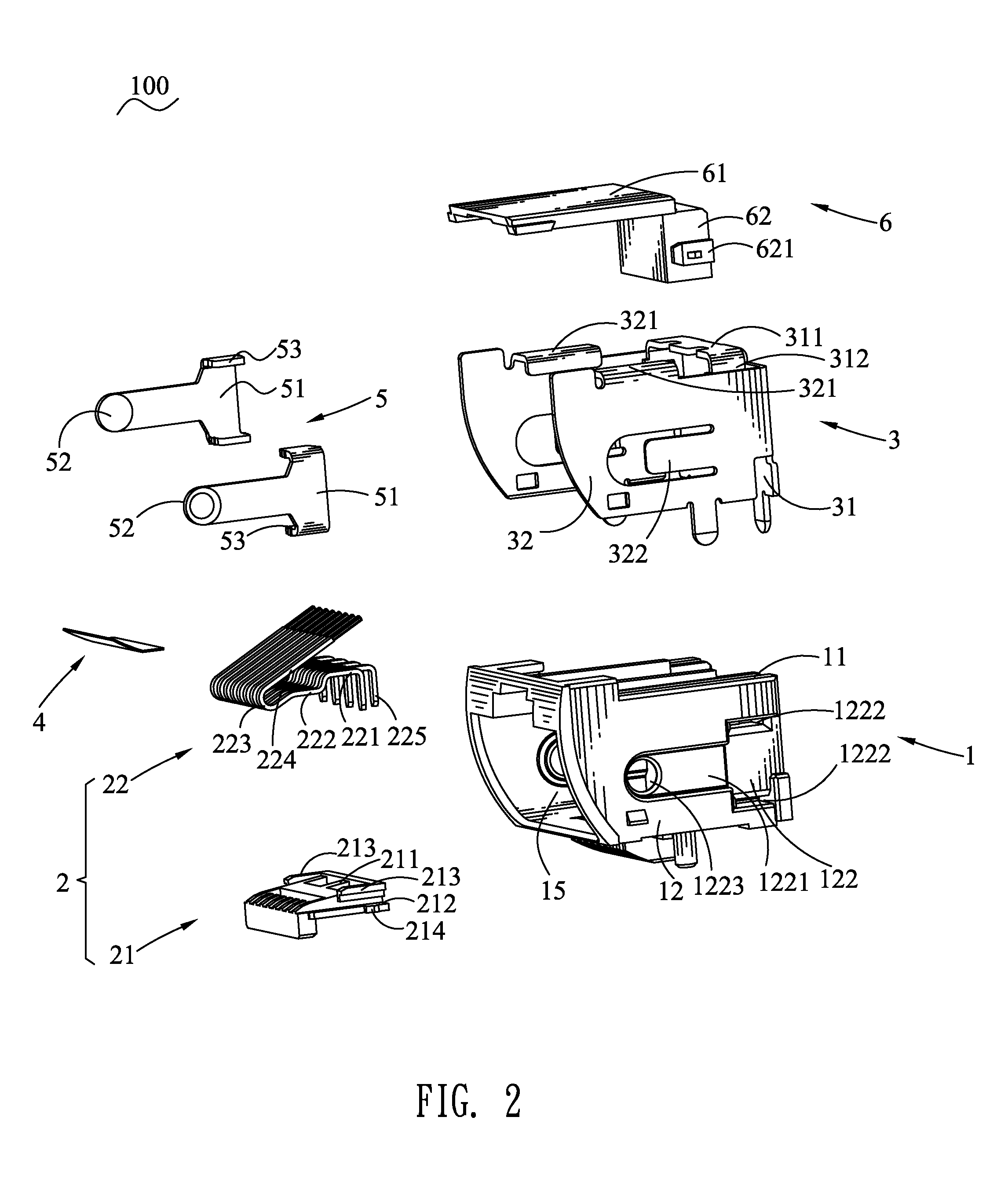
[0016]With reference to FIG. 1 and FIG. 2, a receptacle connector 100 in accordance with the present invention includes an insulating housing 1, a terminal module 2, a shielding shell 3, an insulating slice 4, two clipping elements 5 and a cover 6.

[0017]Referring to FIG. 2, FIG. 3 and FIG. 4, the insulating housing 1 defines a top wall 11, two side walls 12, a bottom wall 13 opposite to the top wall 11 and a rear wall 14 connected with rear edges of the top wall 11, the side walls 12 and the bottom wall 13. The top wall 11, the side walls 12, the bottom wall 13 and the rear wall 14 are interconnected to form an accommodating chamber 15 thereamong. Two sides of the top wall 11 respectively define a fastening slot 111 passing through the rear wall 14. A middle of the top wall 11 defines an opening groove 112 penetrating therethrough and passing through an upper portion of the rear wall 14. Tops of fronts of inner sidewalls of the opening groove 112 protrude face to face to form two su...


PUM


Abstract

An insulating housing defines an accommodating chamber and a receiving cavity in a bottom thereof. The bottom of the insulating housing defines a plurality of first terminal passages arranged at intervals along a traverse direction thereof and extends longitudinally to penetrate therethrough. The first terminal passages communicate with the accommodating chamber. A plurality of second terminal passages are arranged at intervals along a traverse direction thereof. A terminal module includes a terminal base disposed in the receiving cavity and a plurality of terminals molded together with the terminal base and arranged side by side. Each terminal has a fastening portion. A front end of the fastening portion extends forward to form a connecting portion which is arched upward and rearward to form a substantially oblique U-shaped bending portion. A free end of the bending portion extends along a tangent direction thereof to form a contacting portion.

Description

BACKGROUND OF THE INVENTION[0001]1. Field of the Invention[0002]The present invention generally relates to a receptacle connector, and more particularly to a receptacle connector with a terminal module capable of avoiding elastic deformation of terminals thereof.[0003]2. The Related Art[0004]A traditional receptacle connector for connecting with a mating plug connector generally includes a square insulating housing, a terminal module and a shielding shell. The insulating housing defines an accommodating chamber penetrating through a mating surface thereof for receiving a plug connector therein. The terminal module includes a plurality of terminals and a terminal base. Each of the receptacle terminals has a fixing portion, one end of the fixing portion extends perpendicularly to form a soldering portion, the other end of the fixing portion is bent opposite to the soldering portion to form a bending portion, a free end of the bending portion extends rearward to form a connecting porti...

Claims


Application Information

Patent Timeline
Patent Type & Authority Patents(United States)
IPC IPC(8): H01R13/648
CPCH01R12/724H01R13/5045H01R13/6583H01R24/64
Inventor SUN, YANCHANG, KAI-HSIANGLIN, KUO-CHIN
Owner CHENG UEI PRECISION IND CO LTD
Learn More