Marine vessel propulsion unit

a propulsion unit and marine technology, applied in marine propulsion, vessel construction, propulsive elements, etc., can solve the problems of absorbing torque applied to the propeller shaft, high torque and insufficient absorption of so as to reduce the shock applied to the propeller shaft, reduce the shock reduction mechanism and minimize the effect of the shock reduction mechanism

Active Publication Date: 2010-05-27
YAMAHA MOTOR CO LTD
View PDF6 Cites 8 Cited by
  • Summary
  • Abstract
  • Description
  • Claims
  • Application Information

AI Technical Summary

Benefits of technology

[0008]That is, in the marine vessel propulsion unit according to the above-described prior art, when a shock applied to the propeller shaft is absorbed, the plurality of drive teeth move forward along the drive shaft while sliding on the plurality of driven teeth. Therefore, the plurality of drive teeth and the plurality of driven teeth may be worn away. Also, if the plurality of drive teeth and the plurality of driven teeth are worn away, the life of a mechanism arranged to reduce the shock, including the plurality of drive teeth and the plurality of driven teeth, will be shortened.
[0011]In order to overcome the previously unrecognized and unsolved challenges described above, a preferred embodiment of the present invention provides a marine vessel propulsion unit including an engine, a drive shaft, a propeller shaft, a propeller, an intermediate shaft, a forward-reverse switching mechanism, and a shock reduction mechanism. The drive shaft is arranged to be rotated by the engine. The rotation of the drive shaft is transmitted to the propeller shaft. The propeller is arranged to be rotated together with the propeller shaft. The intermediate shaft is arranged on a central rotation axis of the propeller shaft. The intermediate shaft is arranged to transmit rotation between the drive shaft and the propeller shaft. The forward-reverse switching mechanism is arranged to switch a rotational direction of the propeller shaft to a forward drive direction or a reverse drive direction. The shock reduction mechanism includes a plurality of spring members and a pair of stopper portions. The shock reduction mechanism is arranged on the central rotation axis of the propeller shaft. The plurality of spring members are arranged to absorb a force in the rotational direction by elastically deforming in the rotational direction when the force in the rotational direction is applied to the intermediate shaft. The pair of stopper portions are arranged to prevent elastic deformations of the plurality of spring members by coming into contact with each other when the elastic deformation amounts of the plurality of spring members reach a predetermined value.
[0013]With this arrangement, the drive shaft is rotated by the engine, and the rotation of the drive shaft is transmitted to the intermediate shaft. Then, the rotation of the intermediate shaft is transmitted to the propeller shaft, and the propeller shaft and the propeller rotate integrally. Accordingly, a propulsion force is generated. Therefore, when the rotational direction of the propeller shaft is set to the forward drive direction by the forward-reverse switching mechanism, a propulsion force to propel the hull forward is generated. Also, when the rotational direction of the propeller shaft is set to the reverse drive direction by the forward-reverse switching mechanism, a propulsion force to propel the hull backward is generated. Also, a shock which is applied to the propeller shaft when switching the rotational direction of the propeller shaft by the forward-reverse switching mechanism is reduced and minimized by the shock reduction mechanism.
[0014]In detail, for example, when switching the rotational direction of the propeller shaft by the forward-reverse switching mechanism, a shock in the rotational direction may be applied to the intermediate shaft and this shock may be transmitted to the propeller shaft. The shock in the rotational direction to be applied to the intermediate shaft at this time is absorbed by elastic deformations of the plurality of spring members. Accordingly, the shock to be applied to the propeller shaft is reduced and minimized by the shock reduction mechanism. Also, the shock is absorbed by the elastic deformations of the plurality of spring members, such that wearing of the members provided with the shock reduction mechanism is reduced and minimized as compared with the marine vessel propulsion unit according to the prior art described above. Accordingly, the life of the shock reduction mechanism is improved. Further, the plurality of spring members are arranged such that even when a great shock is applied to the intermediate shaft, the shock is reliably absorbed. Furthermore, when the elastic deformation amounts of the spring members reach a predetermined value, the pair of stopper portions come into contact with each other and prevent the elastic deformations of the spring members. Therefore, after the pair of stopper portions come into contact with each other, a torque applied to the intermediate shaft is transmitted to the propeller shaft without being absorbed by the plurality of spring members. Accordingly, a high torque is transmitted to the propeller.
[0018]Also, the first relative rotation member may include a projection, and the second relative rotation member may include a support portion. In this case, the projection may be arranged to press the first housed member in one rotational direction when the first and second relative rotation members rotate relatively in the one rotational direction. Further, the projection may be arranged to press the second housed member in the other rotational direction when the first and second relative rotation members rotate relatively in the other rotational direction. Also, the support portion maybe arranged to support the first and second housed members so as to prevent rotation in the other rotational direction of the first housed member and rotation in the one rotational direction of the second housed member.

Problems solved by technology

Therefore, the shock applied to the propeller shaft may not be sufficiently absorbed.
Therefore, when propelling the hull, a high torque must be applied to the propeller.
Therefore, there is a possibility that the torque applied to the propeller shaft is absorbed by the spring member and a high torque is not transmitted to the propeller.

Method used


Image

  • Marine vessel propulsion unit
  • Marine vessel propulsion unit
  • Marine vessel propulsion unit

Examples


first preferred embodiment

[0048]First, an arrangement of an outboard motor according to a first preferred embodiment of the present invention will be described with reference to FIG. 1 to FIG. 6. FWD in the figures indicates a forward drive direction of the marine vessel, and BWD in the figures indicates a reverse drive direction of the marine vessel.

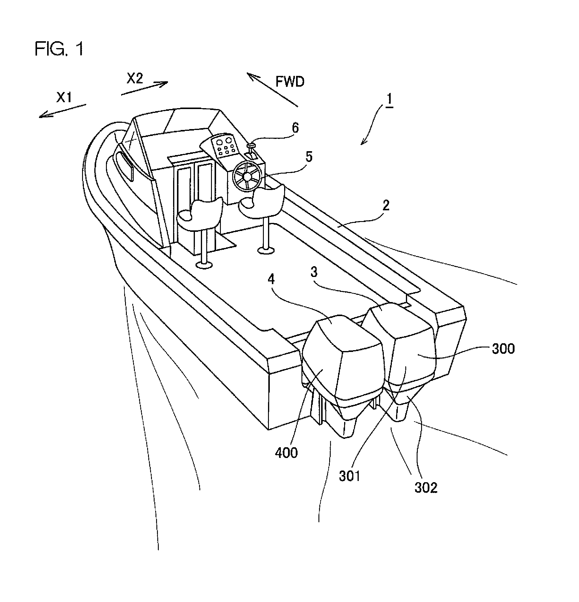
[0049]FIG. 1 is a perspective view of a marine vessel equipped with an outboard motor according to a first preferred embodiment of the present invention.

[0050]The marine vessel 1 includes a hull 2 floating on the water surface, two outboard motors 3 and 4 attached to the rear portion of the hull 2, a steering portion 5 for steering the hull 2, and a control lever portion 6 arranged in the vicinity of the steering portion 5. The hull 2 is propelled forward or backward by the two outboard motors 3 and 4. Forward driving and reverse driving of the hull 2 are switched by operating the control lever portion 6. The outboard motors 3 and 4 are an example of the “marine...

second preferred embodiment

[0133]Next, an arrangement of an outboard motor of a second preferred embodiment of the present invention will be described with reference to FIG. 7 to FIG. 15. FWD in the figures indicates the forward drive direction, and BWD in the figures indicates the reverse drive direction. In FIG. 7 to FIG. 15, components equivalent to the components shown in FIG. 1 to FIG. 6 will be designated by the same reference numerals as in FIG. 1, etc., and description thereof will be omitted.

[0134]This second preferred embodiment is different from the first preferred embodiment described above mainly in that all spring members of the shock reduction mechanism are simultaneously compressed and a shock to be applied to the propeller shaft is reduced and minimized even when the shock in either rotational direction of the forward drive direction and the reverse drive direction is applied to the propeller shaft.

[0135]FIG. 7 is a sectional view for describing an arrangement inside a lower case of the outbo...

third preferred embodiment

[0178]Next, an arrangement of an outboard motor of a third preferred embodiment of the present invention will be described with reference to FIG. 16 and FIG. 17. FWD in the figures indicates the forward drive direction, and BWD in the figures indicates the reverse drive direction. In FIG. 16 and FIG. 17, components equivalent to the components shown in FIG. 1 to FIG. 15 will be designated by the same reference numerals as in FIG. 1, etc., and description thereof will be omitted.

[0179]The present third preferred embodiment is different from the first preferred embodiment mainly in that the reduction gear mechanism (planetary gear mechanism) is not provided between the intermediate shaft and the propeller shaft, and the shock reduction mechanism is provided between the intermediate shaft and the propeller shaft.

[0180]FIG. 16 is a sectional view for describing an arrangement inside a lower case of the outboard motor according to the third preferred embodiment of the present invention. ...


PUM


Abstract

A marine vessel propulsion unit includes an engine, a drive shaft, a propeller shaft, a propeller, an intermediate shaft, a forward-reverse switching mechanism, and a shock reduction mechanism. The intermediate shaft is arranged on a central rotation axis of the propeller shaft. The intermediate shaft is arranged to transmit rotation between the drive shaft and the propeller shaft. The forward-reverse switching mechanism is arranged to switch a rotational direction of the propeller shaft to a forward drive direction or a reverse drive direction. The shock reduction mechanism includes a plurality of spring members and a pair of stopper portions. The shock reduction mechanism is arranged on the central rotation axis of the propeller shaft. The plurality of spring members are arranged to absorb a force in the rotational direction by elastically deforming in the rotational direction when the force in the rotational direction is applied to the intermediate shaft. The pair of stopper portions are arranged to prevent elastic deformations of the plurality of spring members by coming into contact with each other when the elastic deformation amounts of the plurality of spring members reach a predetermined value.

Description

BACKGROUND OF THE INVENTION[0001]1. Field of the Invention[0002]The present invention relates to a marine vessel propulsion unit.[0003]2. Description of Related Art[0004]A prior art marine vessel propulsion unit is described in U.S. Pat. No. 6,547,613. The marine vessel propulsion unit includes a propeller shaft, a propeller to be rotated together with the propeller shaft, and a forward-reverse switching mechanism which applies a driving force from an engine to the propeller shaft and rotates the propeller shaft in a forward drive direction or a reverse drive direction. The propeller shaft includes a drive shaft and a driven shaft extending in the front / rear direction.[0005]The drive shaft and the driven shaft are joined by engagement between a plurality of drive teeth provided on the drive shaft and a plurality of driven teeth provided on the driven shaft. The plurality of drive teeth are arranged to be slidable in the front / rear direction along the drive shaft. Also, the plurality...

Claims


Application Information

Patent Timeline
Patent Type & Authority Applications(United States)
IPC IPC(8): B63H23/00B63H23/34B63H21/38F16H57/08
CPCB63B2770/00B63H20/14B63H20/20F16D3/66B63H2023/0283B63H2023/342F16D3/12B63H23/34
Inventor OKABE, YOSHIHIKO
Owner YAMAHA MOTOR CO LTD
Why Eureka
Try Eureka