Board connector and method of mounting it

a technology of connectors and connectors, applied in the direction of securing/insulating coupling contact members, coupling device connections, printed circuits, etc., can solve the problems of dislocation of dislocating members, and achieve the effects of widening the insertion space, preventing a resilient deformation of the projection, and improving locking reliability

Inactive Publication Date: 2011-11-17
SUMITOMO WIRING SYST LTD
View PDF7 Cites 8 Cited by
  • Summary
  • Abstract
  • Description
  • Claims
  • Application Information

AI Technical Summary

Benefits of technology

[0007]The invention relates to a board connector with a housing that is to be mounted on a circuit board. The housing has at least one projection to be inserted into a respective mounting hole of the circuit board. The connector also has at least one displacing member to be mounted displaceably relative to the housing. The displacing member is formed with at least one inserting portion and the projection is formed with an insertion space for receiving the inserting portion. The displacing member is displaced in the process of mounting the housing on the circuit board due to interference with the circuit board. The projection is inserted into the mounting hole of the circuit board and the inserting portion is inserted toward a back side of the insertion space. A leading end of the projection engages an opening edge of the mounting hole of the circuit board when the housing is mounted completely on the circuit board. Thus, the housing is fixed to the circuit board by a one-touch mounting operation. Additionally, the inserting portion is inserted farther toward the back of the insertion space and deforms the projection to widen the insertion space and to prevent a resilient deformation of the projection. Accordingly, the housing is fixed to the circuit board with improved locking reliability and enhanced locking strength.
[0008]Terminal fittings are pulled out to project from the housing. The displacing member preferably is an alignment plate with positioning holes for receiving and positioning the terminal fittings. Thus, the construction of the connector is simplified as compared with the case where a special displacing member is provided separately from the alignment plate. Projecting amounts of the terminal fittings from the positioning holes increase as the alignment plate is displaced in the mounting process of the housing. Thus, the terminal fittings are protected by the edges of the positioning holes before the displacement of the alignment plate and the projecting amounts of the terminal fittings from the positioning holes increase to ensure sufficient soldering margins of the terminal fittings to the circuit board after the displacement of the alignment plate.
[0009]A mounting direction of the housing on the circuit board is a thickness direction of the circuit board. The insertion space is open in the thickness direction of the circuit board at the leading end of the projection. Additionally, the inserting portion is displaced in the thickness direction of the circuit board in the insertion space. Thus, the mounting operation of the housing on the circuit board and the displacement of the inserting portion in the insertion space can be linked by a relatively simple construction.

Problems solved by technology

The displacing member is displaced in the process of mounting the housing on the circuit board due to interference with the circuit board.

Method used


Image

  • Board connector and method of mounting it
  • Board connector and method of mounting it
  • Board connector and method of mounting it

Examples


Embodiment Construction

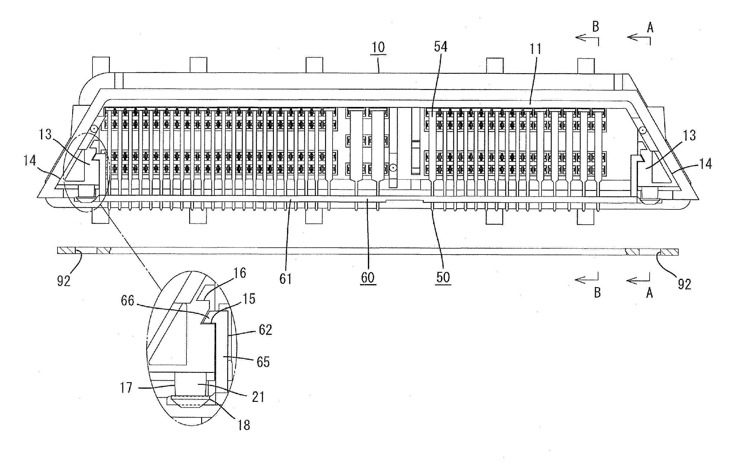
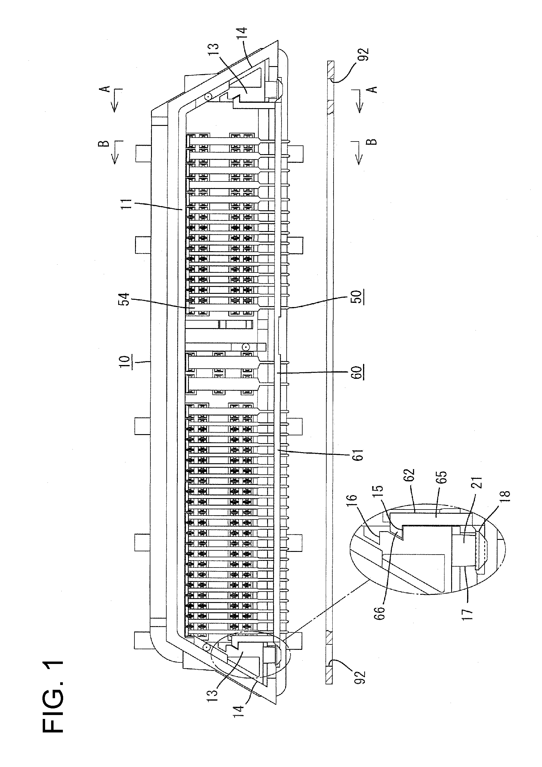
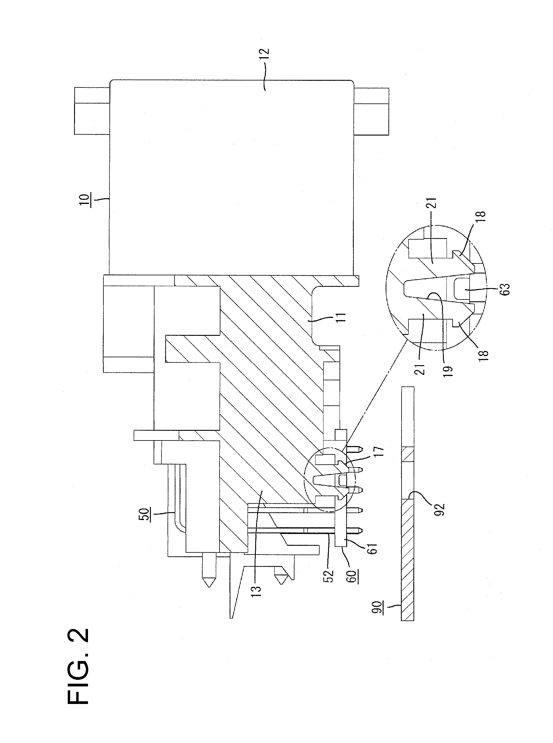
[0026]A board connector in accordance with an embodiment of the invention has a housing 10, terminal fittings 50 and an alignment plate 60. The housing 10 is mountable on a device such as a printed circuit board 90 and is connectable to an unillustrated mating housing. In the following description, an end to be connected with the mating housing is referred to as the front end concerning forward and backward directions and an end of the board 90 on which the housing 10 is to be mounted is referred to as an upper side concerning a vertical direction.

[0027]The housing 10 is made e.g. of synthetic resin and has a flat shape that is long and narrow in a width direction. The housing 10 includes a terminal mounting portion 11 substantially in the form of a back plate, through which the terminal fittings 50 are to be mounted. A rectangular tubular receptacle 12 projects forward from the peripheral edge of the terminal mounting portion 11, as shown in FIGS. 1, 6 and 10.

[0028]Each terminal fi...


PUM


Abstract

A housing (10) has inserting portions (63) with projections (17) formed with slits (19). An alignment plate (60) is mounted movably on the housing (10) and has inserting portions (63) that enter the slits (19) of the projections (17). The alignment plate (60) is displaced relative to the housing (10) in the process of mounting a housing (10) on a board (90) due to interference with the board (90) and the inserting portions (63) move deeper into the slits (19). The projections (17) widen the slits (19) as the inserting portions (63) move deeper into the slits (19) and hence leading ends of the projections (17) engage opening edges of the mounting holes (92) of the board (90) to fix the housing (10) to the board (90).

Description

BACKGROUND OF THE INVENTION[0001]1. Field of the Invention[0002]The invention relates to a board connector.[0003]2. Description of the Related Art[0004]Japanese Unexamined Patent Publication No. H09-283241 discloses a conventional board connector. This connector includes a housing to be mounted on a circuit board and an alignment plate mounted on the housing. The alignment plate has positioning holes that receive and position leading ends of terminal fittings pulled out from the housing. Two legs project from the bottom surface of the housing and engage the circuit board. Screws penetrate through the circuit board and engage the legs to fix the housing to the circuit board. The use of screws to fix the above-described housing on the circuit board requires a separate series of operational steps and creates a large operational burden.[0005]Clips have been considered in place of screws to provide a one-touch operation for fixing a housing to a circuit board. The clips could be inserted...

Claims


Application Information

Patent Timeline
Patent Type & Authority Applications(United States)
IPC IPC(8): H01R13/40
CPCH01R12/724H01R12/7023
Inventor TONOSAKI, TAKASHI
Owner SUMITOMO WIRING SYST LTD
Why Eureka
Try Eureka