Connector having an improved front holder design for retaining terminals

a technology of front holder and retaining terminal, which is applied in the direction of securing/insulating coupling contact members, coupling device connections, electrical apparatus, etc., can solve the problems of poor operability, inability to provide retaining portions in a small-size connector, and the operator cannot easily effect one-touch operation

Inactive Publication Date: 2005-03-01
YAZAKI CORP
View PDF11 Cites 8 Cited by
  • Summary
  • Abstract
  • Description
  • Claims
  • Application Information

AI Technical Summary

Benefits of technology

It is therefore an object of the present invention to provide a connector, in which the locking of a front holder in a completely-retaining position can be canceled with a one-touch operation, and the efficiency of an operation for returning the front holder from the completely-retaining position to a provisionally-retaining position is high.
a front holder, attached to the housing in a completely-retaining position through a provisionally-retaining position;wherein the front holder prevents the elastic deformation of the elastic retaining arm portions in the completely-retaining position; andwherein the front holder allows the elastic deformation of the elastic retaining arm portions in the provisionally-retaining position;
In the above configurations, the locking force of the center retaining member is exerted at the central portions of the housing and front holder, so that the locking of the front holder in the completely-retaining position is stable.
In the above configuration, a dead space, used for removing the mold, is efficiently used.
a front holder, inserted into the housing from a fitting side of the housing, and attached to the housing in a completely-retaining position through a provisionally-retaining position;wherein the front holder prevents the elastic deformation of the elastic retaining arm portions in the completely-retaining position; andwherein the front holder allows the elastic deformation of the elastic retaining arm portions in the provisionally-retaining position;
In the above configurations, the movement of the front holder between the provisionally-retaining position and the completely-retaining position is effected positively and smoothly.

Problems solved by technology

In the related connector 50, however, when the front holder 53 is to be returned from the completely-retaining position to the provisionally-retaining position, the pair of right and left operating plates 59 must be operated at the same time, and therefore the operator can not easily effect this operation in a one-touch manner, which has invited a problem that the operability is bad.
Therefore, these retaining portions can not be provided in a small-size connector in which small metal terminals are used, and the distance between adjacent terminal receiving chambers is small, and each terminal receiving chamber is formed by a small space.
Even if such retaining portions can be provided, the desired position-holding force can not be obtained.
Thus, these problems have been encountered.

Method used


Image

  • Connector having an improved front holder design for retaining terminals
  • Connector having an improved front holder design for retaining terminals
  • Connector having an improved front holder design for retaining terminals

Examples


first embodiment

the present invention will now be described with reference to the drawings,

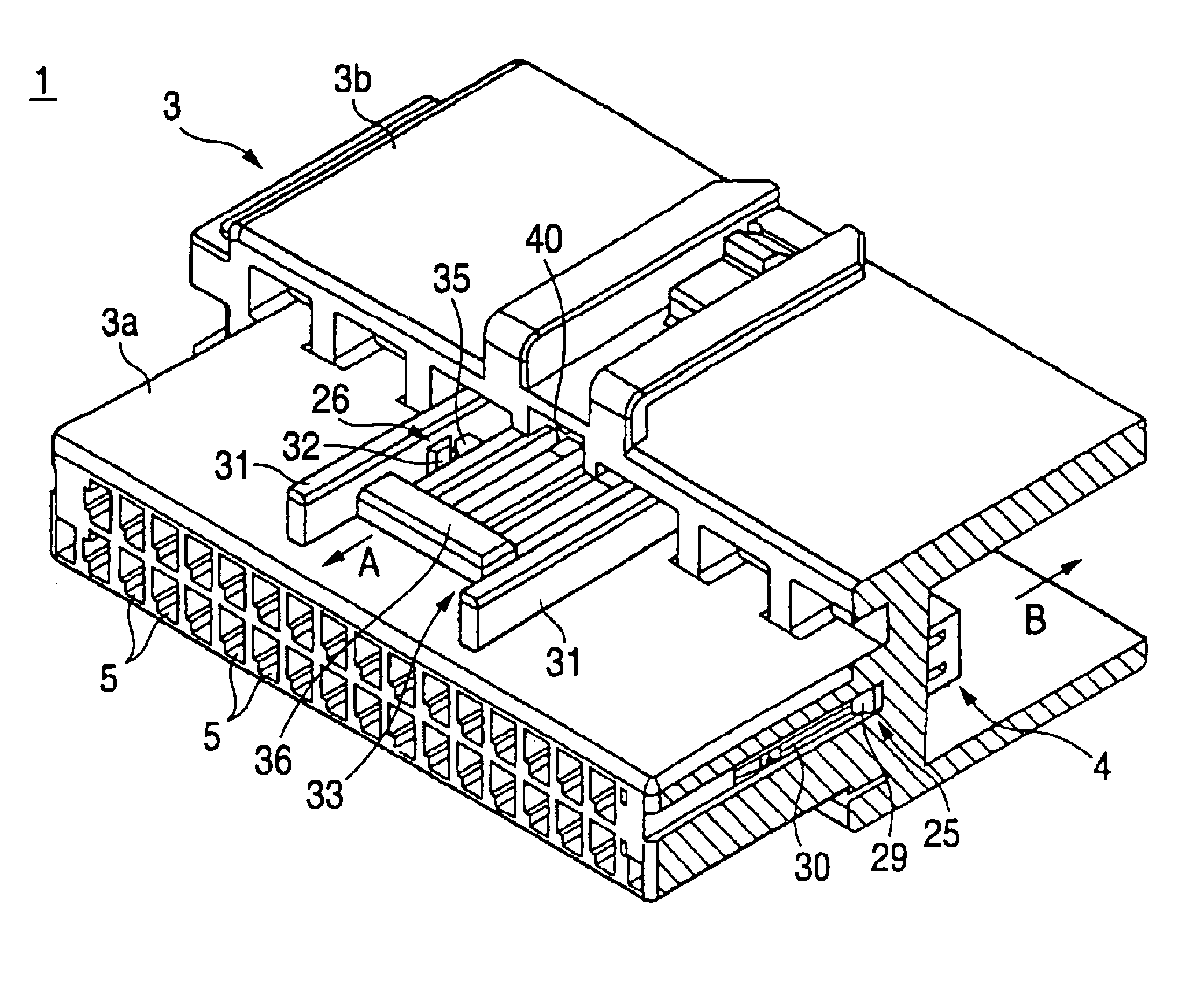
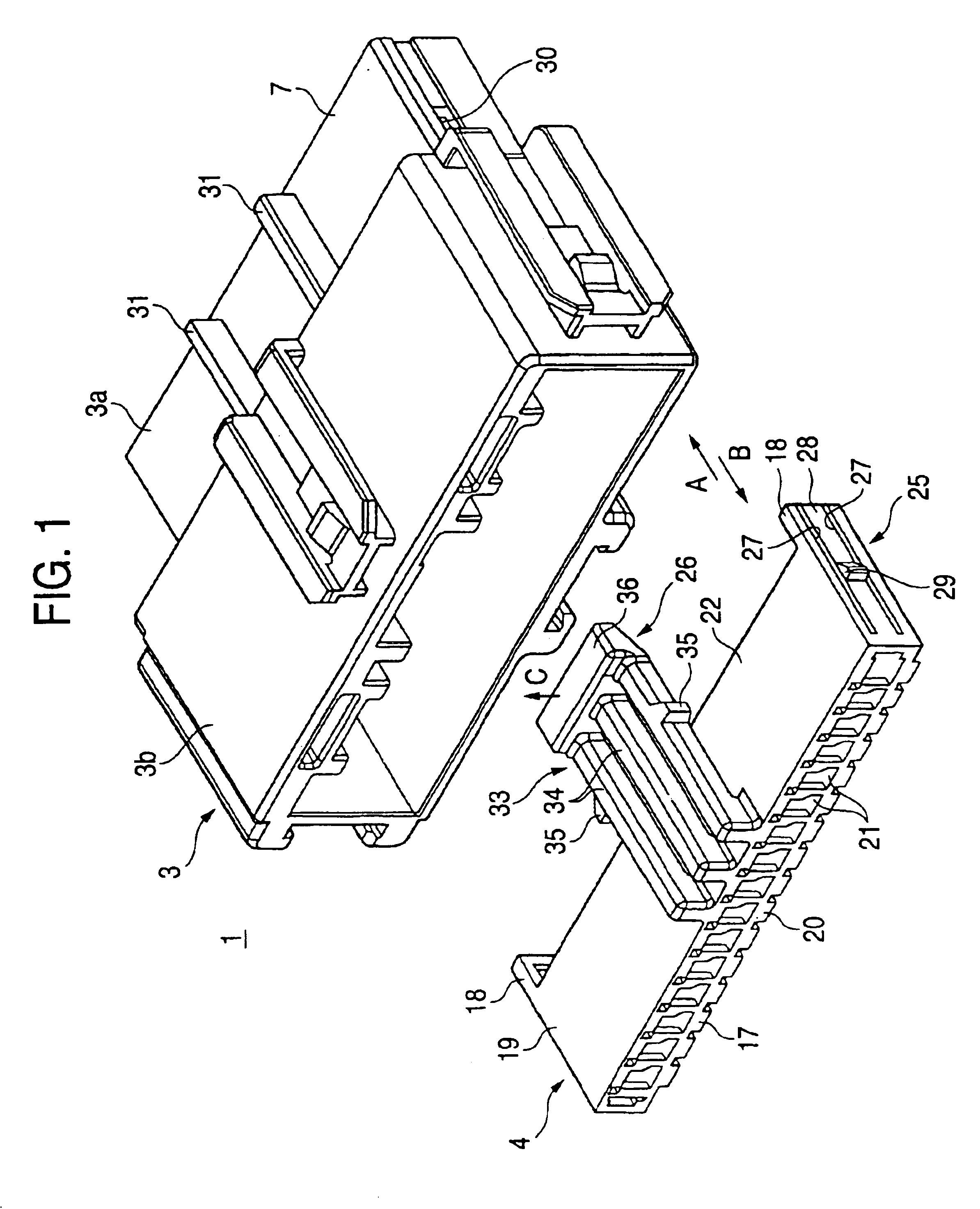
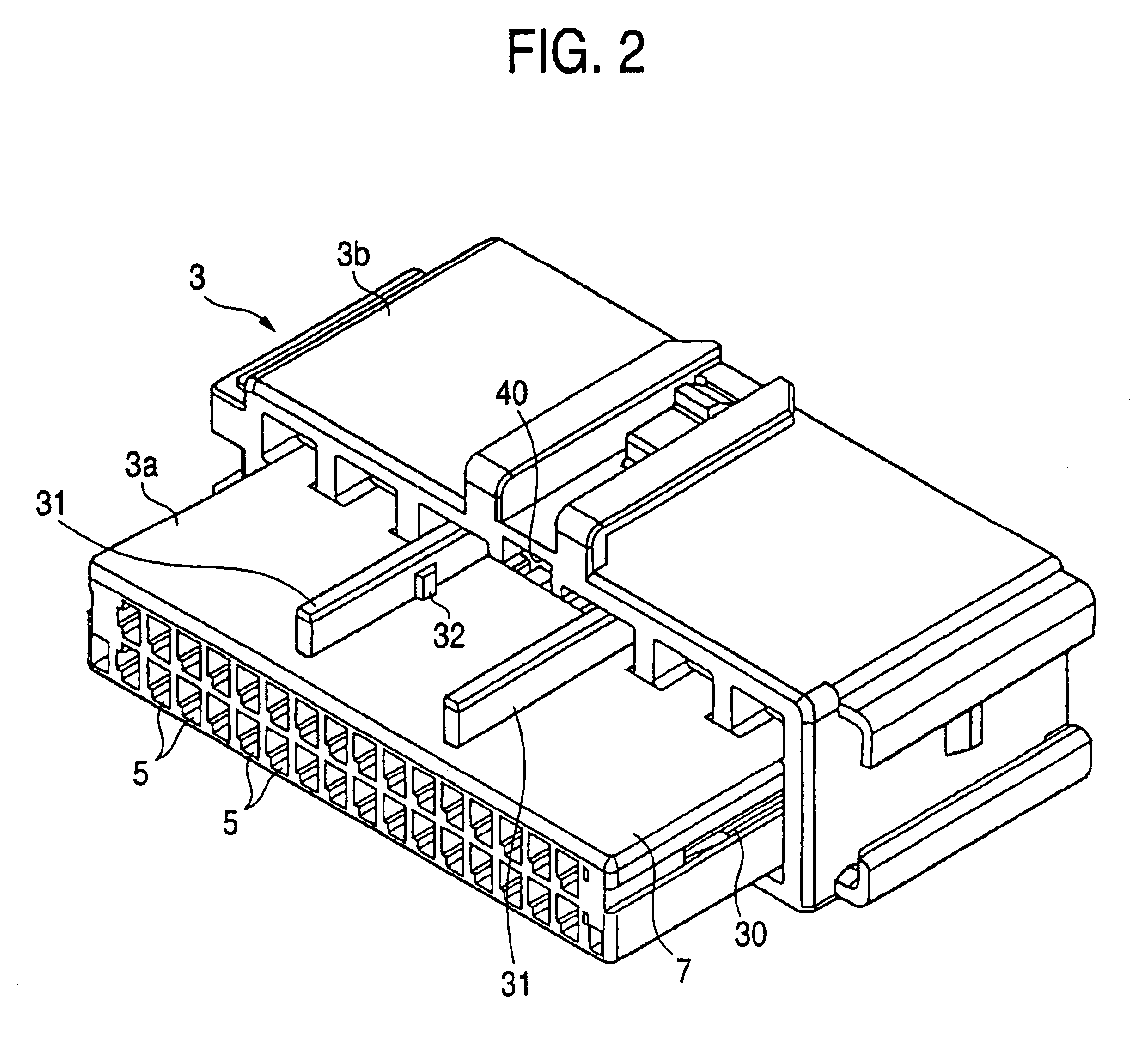
FIGS. 1 to 7 show the first embodiment of the invention, and FIG. 1 is an exploded, perspective view showing a housing 3 and a front holder 4, FIG. 2 is a perspective view of the housing 3 as seen from a direction opposite to the direction from which this housing is seen in FIG. 1, FIG. 3 is a partly-broken perspective view of a connector 1, showing side retaining member 25, with the front holder 4 located in a provisionally-retaining position, and FIG. 4 is a partly-broken perspective view of the connector 1, showing center retaining member 26, with the front holder 4 located in the provisionally-retaining position, FIG. 5 is a perspective view of the connector 1, showing a condition in which the front holder 4 is located in a completely-retaining position, FIG. 6 is a partly-broken perspective view of the connector 1, showing the side retaining member 25, with the front holder 4 located in the completely-re...


PUM


Abstract

A connector includes a housing, a front holder, a provisionally-retaining member and a completely-retaining member. The housing includes terminal receiving chambers in which metal terminals are accommodated and a plurality of elastic retaining arm portions for respectively retaining the metal terminals. The front holder is attached to the housing in a completely-retaining position through a provisionally-retaining position. The front holder prevents elastic deformation of the elastic retaining arm portions in the completely-retaining position but allows elastic deformation of the elastic retaining arm portions in the provisionally-retaining position. The completely-retaining member retains the front holder to the housing in the completely-retaining position and includes an operation portion for releasing the retaining of the housing and the holder, which is exposed to the exterior.

Description

BACKGROUND OF THE INVENTIONThis invention relates to a connector in which a front holder is attached to a housing, thereby preventing the withdrawal of metal terminals provided within the housing.FIGS. 15 to 17 show a first related connector of this kind disclosed in JP-A-9-251874. As shown in FIGS. 15 to 17, this connector 50 includes a plurality of metal terminals (not shown) connected respectively to end portions of wires, a housing 52 for receiving the plurality of metal terminals therein, and a front holder 53 attached to the housing 52.The housing 52 has many terminal receiving chambers 54 formed therein, and the metal terminals are received in these terminal receiving chambers 54, respectively. An elastic retaining arm portion (not shown) is provided in a projected manner in each terminal receiving chamber 54, and is supported at one end thereof on an upper face of the terminal receiving chamber 54. The metal terminal is retained by this elastic retaining arm portion. Slide g...

Claims


Application Information

Patent Timeline
Patent Type & Authority Patents(United States)
IPC IPC(8): H01R13/436
CPCH01R13/4365
Inventor TAKAHASHI, TOSHIHARUSUZUKI, MOTOYOSHI
Owner YAZAKI CORP
Why Eureka
Try Eureka