Providing a common environment for multiple MEMS devices

Inactive Publication Date: 2011-08-16
QORVO US INC
View PDF11 Cites 9 Cited by
  • Summary
  • Abstract
  • Description
  • Claims
  • Application Information

AI Technical Summary

Benefits of technology

[0014]The present invention relates to providing a uniform operating environment for each of multiple devices by providing a common environment to the devices. The common environment is provided by multiple cavities, which are interconnected by at least one environmental pathway, which may be provided by at least one tunnel. The common environment may help provide uniform operating pressure, which may be a partial or near vacuum, a surrounding gas of uniform contents, such as an inert gas or mixture of inert gases, or both. The devices may include micro-electro-mechanical system (MEMS) devices, such as MEMS switches.
[0016]To close any one the active MEMS switches, the switch control circuitry will apply the adaptive actuation signal, which was derived from analyzing the closing of the test MEMS switch, to the active MEMS switch. Application of the actuation signal should result in a soft closing, or at least a near closing, of the active MEMS switch. To maintain the active MEMS switch closed, a hold signal is applied at the closing time. Given the near closing or soft closing in response to the actuation signal and the timely application of the subsequent hold signal, bouncing of the movable member, such as the cantilever, in the active MEMS switch is minimized, if not completely eliminated.
[0017]In another embodiment of the present invention, the switch control circuitry may provide a release signal configured to reduce or minimize ringing, which is normally associated with opening a MEMS switch from a closed position. When the hold signal is released, a release signal is applied to the actuator plate to effectively counter or slow the rate at which the movable member actually moves back toward the normal resting position. The normal resting position generally corresponds to a non-actuated state. By slowing down the rate at which the cantilever returns to a normal resting position after closing, mechanical oscillations are controlled, and thus, ringing of the active MEMS switches is minimized or eliminated.

Problems solved by technology

Such bouncing degrades circuit performance and effectively increases the closing time.
The dynamic closing forces may also be sufficient to damage both the contact portion 24 of the second conductive pad 26 as well as the cantilever contact 22, thus causing excessive wear, which results in a shortened operating life for the MEMS switch 12.
In practice however, process variation in the switch manufacture will reduce or eliminate the efficiency of a single waveform to effect soft closing as described.
Conversely, if the gap between the cantilever 16 and the actuator plate 28 decreases due to manufacturing variation the nominal actuation signal may be too much, thus causing a hard closing, which may induce bouncing or damage.

Method used


Image

  • Providing a common environment for multiple MEMS devices
  • Providing a common environment for multiple MEMS devices
  • Providing a common environment for multiple MEMS devices

Examples


first embodiment

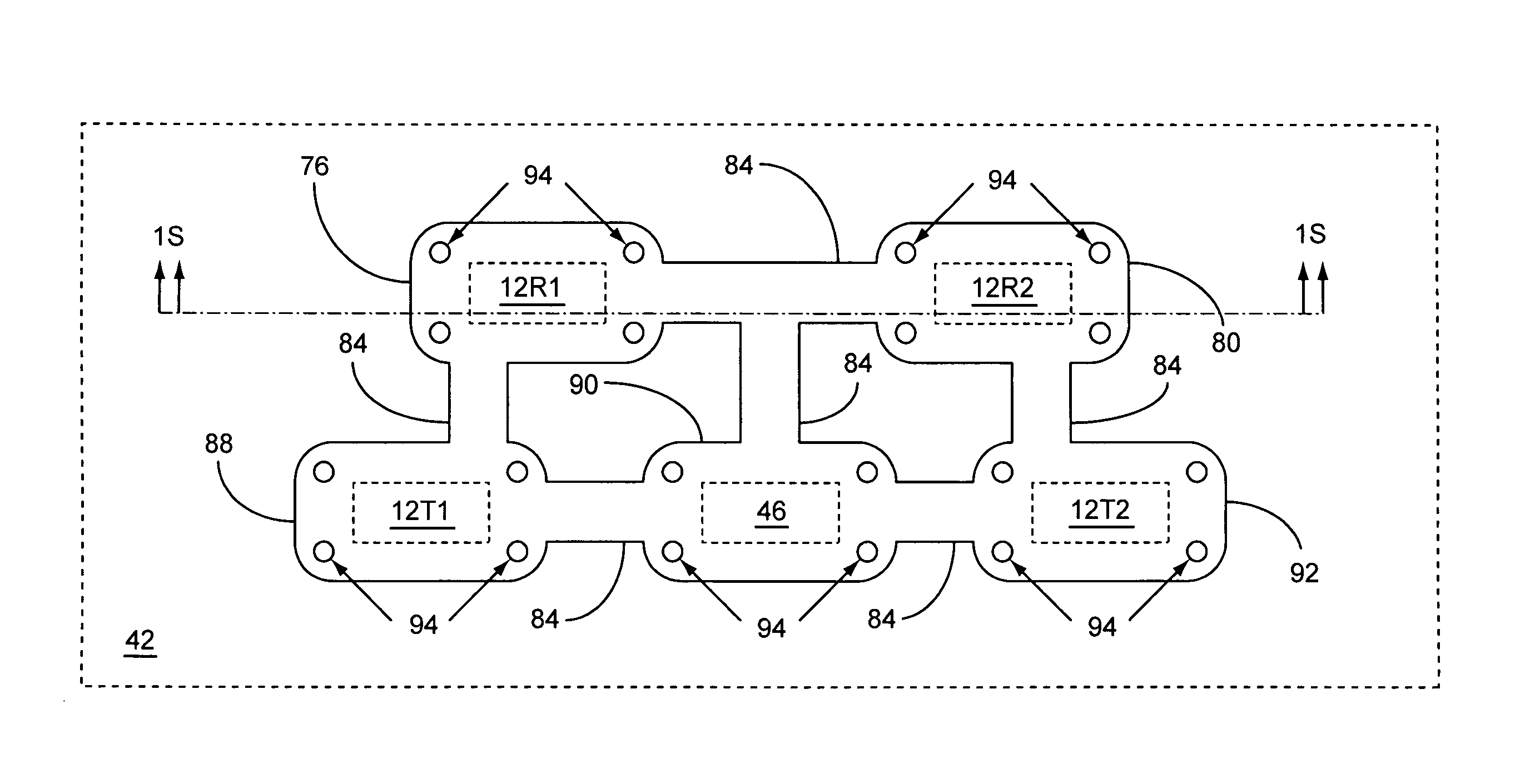
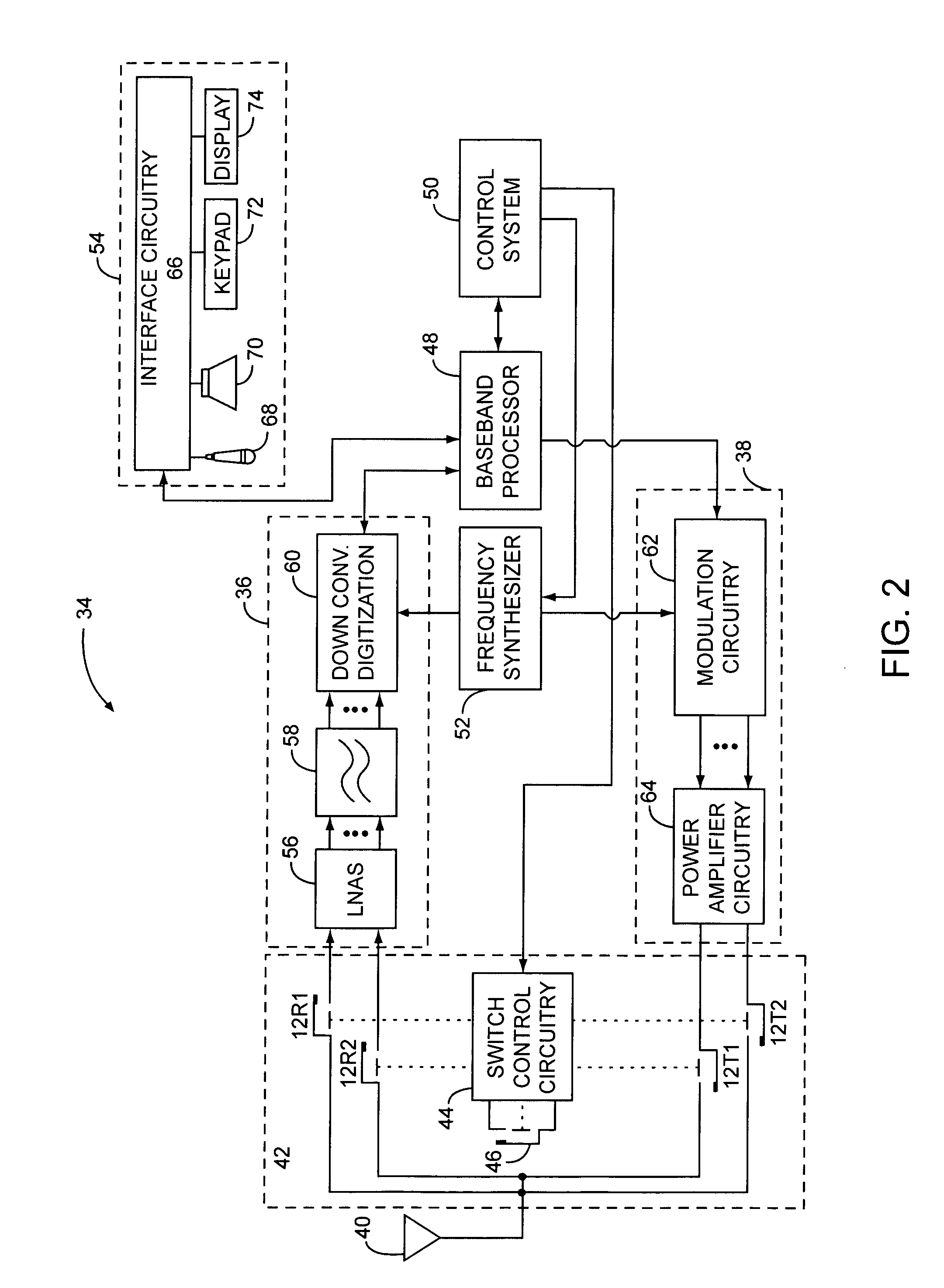
[0066]FIG. 11A shows a partial cross-section 1S of the transmit / receive switch 42 illustrated in FIG. 2, according to the present invention. The first and second active MEMS receive switches 12R1, 12R2 are attached to the substrate 14. The one or more encapsulating layers 30 are used to provide a first MEMS encapsulating dome 76, which forms a first cavity 78 around the first active MEMS receive switch 12R1, and a second MEMS encapsulating dome 80, which forms a second cavity 82 around the second active MEMS receive switch 12R2. A MEMS tunnel 84 interconnects the first and second MEMS encapsulating domes 76, 80 and provides an environmental pathway 86 between the first and second cavities 78, 82. The first and second cavities 78, 82 and the environmental pathway 86 may provide a common environment for the first and second active MEMS receive switches 12R1, 12R2. Therefore a pressure difference between the first and second cavities 78, 82 may be about zero. The common environment may...

second embodiment

[0069]FIG. 12 shows a partial top view of the transmit / receive switch 42 illustrated in FIG. 2, according to the present invention. Instead of the first, second, third, fourth, and fifth MEMS encapsulating domes 76, 80, 88, 90, 92 providing the first, second, third, fourth, and fifth cavities, a first multi-MEMS encapsulating dome 96 provides a first multi-MEMS cavity (not shown) around the first and second active MEMS receive switches 12R1, 12R1, and a second multi-MEMS encapsulating dome 98 provides a second multi-MEMS cavity (not shown) around the first and second active MEMS transmit switches 12T1, 12T2 and the test MEMS switch 46. MEMS tunnels 84 interconnect the first and second multi-MEMS encapsulating domes 96, 98 and provide environmental pathways (not shown) between the first and second multi-MEMS cavities (not shown).

third embodiment

[0070]FIG. 13 shows a partial top view of the transmit / receive switch 42 illustrated in FIG. 2, according to the present invention. Instead of the first, second, third, fourth, and fifth MEMS encapsulating domes 76, 80, 88, 90, 92 providing the first, second, third, fourth, and fifth cavities, a common MEMS encapsulating dome 100 provides a common cavity (not shown) around the active MEMS switches 12R1, 12R2, 12T1, 12T2 and the test MEMS switch 46 to provide the common environment.

[0071]FIG. 14 shows an exploded view of a hybrid cantilever MEMS switch 102, according to one embodiment of the present invention. The hybrid cantilever MEMS switch 102 combines the functionality of the test MEMS switch 46 and one of the active MEMS switches 12R1, 12R2, 12T1, 12T2 into a single MEMS switch. The hybrid cantilever MEMS switch 102 includes the cantilever 16, the anchor 18, a first stationary test contact 104, which may attached to the substrate 14 through contact material, a first movable tes...


PUM


Abstract

The present invention relates to providing a uniform operating environment for each of multiple devices by providing a common environment to the devices. The common environment is provided by multiple cavities, which are interconnected by at least one environmental pathway, which may be provided by at least one tunnel. The common environment may help provide uniform operating pressure, which may be a partial or near vacuum, a surrounding gas of uniform contents, such as an inert gas or mixture of inert gases, or both. The devices may include micro-electro-mechanical system (MEMS) devices, such as MEMS switches.

Description

[0001]This application claims the benefit of U.S. provisional patent application Ser. No. 60 / 941,048 filed May 31, 2007, the disclosure of which is incorporated herein by reference in its entirety.CROSS-REFERENCE TO RELATED APPLICATION[0002]This application is related to U.S. patent application Ser. No. 12 / 117,976 entitled CONTROLLED CLOSING OF MEMS SWITCHES and to U.S. patent application Ser. No. 12 / 118,031 entitled CONTROLLED OPENING OF MEMS SWITCHES, both of which were filed May 9, 2008, and both of which are incorporated herein by reference in their entireties, and form part of the specification and teachings herein.FIELD OF THE INVENTION[0003]The present invention relates to micro-electro-mechanical system (MEMS) devices, such as MEMS switches, and in particular to controlling actuation of MEMS switches to improve performance.BACKGROUND OF THE INVENTION[0004]As electronics evolve, there is an increased need for miniature switches that are provided on semiconductor substrates al...

Claims


Application Information

Patent Timeline
IPC IPC(8): H01H51/22
CPCH01H1/0036H01H1/66H01H59/0009
Inventor DENING, DAVID C.IVANOV, TONYCOSTA, JULIO
Owner QORVO US INC
Why Eureka
Try Eureka