Controlled closing of MEMS switches

a technology of mems switches and control switches, applied in the direction of relays, contact mechanisms, contacts, etc., can solve the problems of excessive wear, increase the closing time, and reduce the circuit performance, so as to reduce or minimize the ringing of active mems switches, reduce the ringing or the effect of reducing or minimizing the ringing ra

Active Publication Date: 2014-02-18
QORVO US INC
View PDF17 Cites 10 Cited by
  • Summary
  • Abstract
  • Description
  • Claims
  • Application Information

AI Technical Summary

Benefits of technology

[0015]To close any one the active MEMS switches, the switch control circuitry will apply the adaptive actuation signal, which was derived from analyzing the closing of the dummy MEMS switch, to the active MEMS switch. Application of the actuation signal should result in a soft closing, or at least a near closing, of the active MEMS switch. To maintain the active MEMS switch closed, a hold signal is applied at the closing time. Given the near closing or soft closing in response to the actuation signal and the timely application of the subsequent hold signal, bouncing of the movable member, such as the cantilever, in the active MEMS switch is minimized, if not completely eliminated.
[0016]In another embodiment of the present invention, the switch control circuitry may provide a release signal configured to reduce or minimize ringing, which is normally associated with opening a MEMS switch from a closed position. When the hold signal is released, a release signal is applied to the actuator plate to slow the rate at which the movable member actually moves back toward the normal resting position. The normal resting position generally corresponds to a non-actuated state. By slowing down the rate at which the cantilever returns to a normal resting position after closing, mechanical oscillations are controlled, and thus, ringing of the active MEMS switches is minimized or eliminated.

Problems solved by technology

Such bouncing degrades circuit performance and effectively increases the closing time.
The dynamic closing forces may also be sufficient to damage both the contact portion 24 of the second conductive pad 26 as well as the cantilever contact 22, thus causing excessive wear, which results in a shortened operating life for the MEMS switch 12.
In practice however, process variation in the switch manufacture will reduce or eliminate the efficiency of a single waveform to effect soft closing as described.
Conversely, if the gap between the cantilever 16 and the actuator plate 28 decreases due to manufacturing variation the nominal actuation signal may be too much, thus causing a hard closing, which may induce bouncing or damage.

Method used


Image

  • Controlled closing of MEMS switches
  • Controlled closing of MEMS switches
  • Controlled closing of MEMS switches

Examples


Embodiment Construction

[0029]The embodiments set forth below represent the necessary information to enable those skilled in the art to practice the invention and illustrate the best mode of practicing the invention. Upon reading the following description in light of the accompanying drawing figures, those skilled in the art will understand the concepts of the invention and will recognize applications of these concepts not particularly addressed herein. It should be understood that these concepts and applications fall within the scope of the disclosure and the accompanying claims.

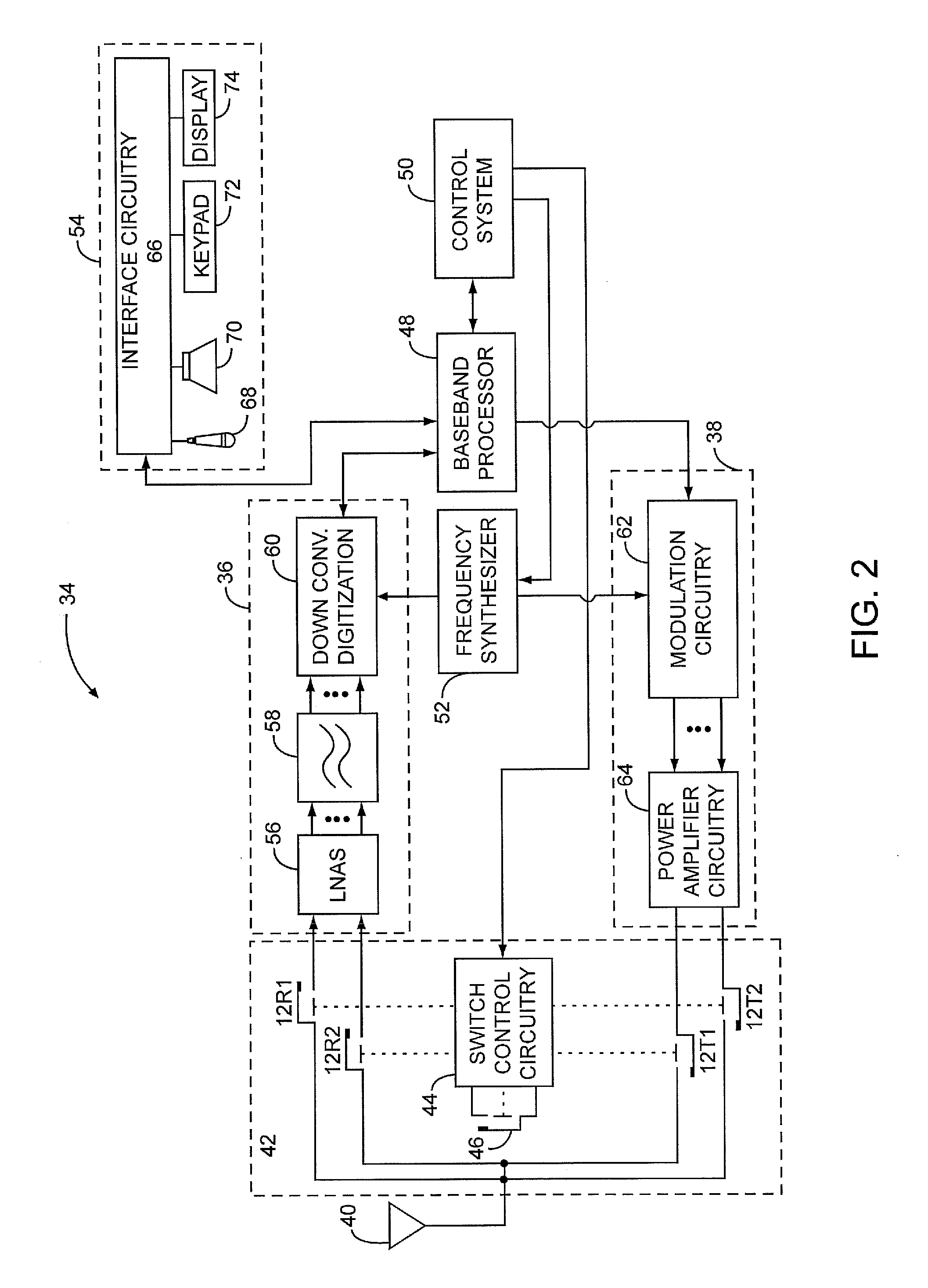
[0030]The present invention may be incorporated in a mobile terminal, such as a mobile telephone, wireless personal digital assistant, or like communication device, in various ways. In many applications, MEMS switches 12 are being deployed as antenna switches, load switches, transmit / receive switches, tuning switches and the like. FIG. 2 illustrates an exemplary embodiment where numerous MEMS switches 12 are employed in a transmit...


PUM


Abstract

For the present invention, multiple MEMS switches that are similar in nature are provided along with switch control circuitry. Of the MEMS switches, one MEMS switch is reserved as a dummy MEMS switch while the one or more remaining MEMS switches are active, and are thus used during normal operation of the electronic circuitry that incorporates the MEMS switches. The switch control circuitry will use the dummy MEMS switch to adaptively determine an actuation signal that is sufficient to effect a near closing or soft closing of the dummy MEMS switch. The switch control circuitry may also determine a closing time that defines a time when the dummy MEMS switch closes relative to application of the actuation signal. The actuation signal and closing time may be updated regularly, if not continuously.

Description

[0001]This application claims the benefit of U.S. provisional patent application Ser. No. 60 / 941,048 filed May 31, 2007, the disclosure of which is incorporated herein by reference in its entirety.CROSS-REFERENCE TO RELATED APPLICATION[0002]This application is related to U.S. patent application Ser. No. 12 / 118,031 entitled CONTROLLED OPENING OF MEMS SWITCHES, which is being filed concurrently, is incorporated herein by reference in its entirety, and forms part of the specification and teachings herein.FIELD OF THE INVENTION[0003]The present invention relates to micro-electro-mechanical system (MEMS) switches, and in particular to controlling actuation of MEMS switches to improve performance.BACKGROUND OF THE INVENTION[0004]As electronics evolve, there is an increased need for miniature switches that are provided on semiconductor substrates along with other semiconductor components to form various types of circuits. These miniature switches often act as relays, and are generally refe...

Claims


Application Information

Patent Timeline
Patent Type & Authority Patents(United States)
IPC IPC(8): H01H3/00
CPCH01H1/66H01H1/0036H01H59/0009Y10T307/76Y10T307/747
Inventor DENING, DAVID C.IVANOV, TONY
Owner QORVO US INC
Why Eureka
Try Eureka