
Gutter cover installation

a gutter cover and installation technology, applied in the field of gutter cover installation, can solve the problems of clogging the flow of rainwater, none of the gutter covers used, and the problems of not being completely solved, and achieve the effect of improving the performan

Active Publication Date: 2011-08-23
JOLY JR ROBERT E +1
View PDF41 Cites 24 Cited by
  • Summary
  • Abstract
  • Description
  • Claims
  • Application Information

AI Technical Summary

Benefits of technology

"The present invention is a gutter cover that has an angled channel and a flexible strip of elastomeric material to prevent water from passing behind the cover. The front side of the cover is formed with a reverse bend and a flared pocket to secure the cover to the gutter outer wall. The cover also has a flattened U-shaped outer edge with a downward angle that acts as a diverter surface to carry off overflow water past the gutter. The technical effects of this invention are improved drainage, prevention of water impoundment, and improved flow of debris away from the cover."

Problems solved by technology

Debris such as twigs and leaves tends to get washed into the gutters and collect to the point of clogging the flow of rainwater.
None of the gutter covers used heretofore have completely solved the problem in all conditions, as clogging and overflow can still occur.
The lack of any support beneath the inner side of the cover will allow it to drop down creating a reverse tilt tending to impound rainwater, which can cause accumulation of debris.
The gutter cover shown therein has perforations allowing drainage into the gutter, but such perforations limit the inflow of rainwater into the gutter and can easily overflow in heavy rain.
Such dam can be ineffective to prevent overflow and can also cause accumulation of debris on the surface of the cover, defeating the purpose of the gutter cover by blocking the perforations and thus cause overflow of the rainwater over the edge of the cover and gutter.
Such overflow can cause unsightly “tiger striping” on the outer wall of the gutter caused by dark discolorations as the rainwater laden with decayed organic material flows down the outside surface of the outer wall of the gutter.
This is a particular problem with light colored gutters.

Method used


Image

  • Gutter cover installation
  • Gutter cover installation
  • Gutter cover installation

Examples


Embodiment Construction

[0029]In the following detailed description, certain specific terminology will be employed for the sake of clarity and a particular embodiment described in accordance with the requirements of 35 USC 112, but it is to be understood that the same is not intended to be limiting and should not be so construed inasmuch as the invention is capable of taking many forms and variations within the scope of the appended claims.

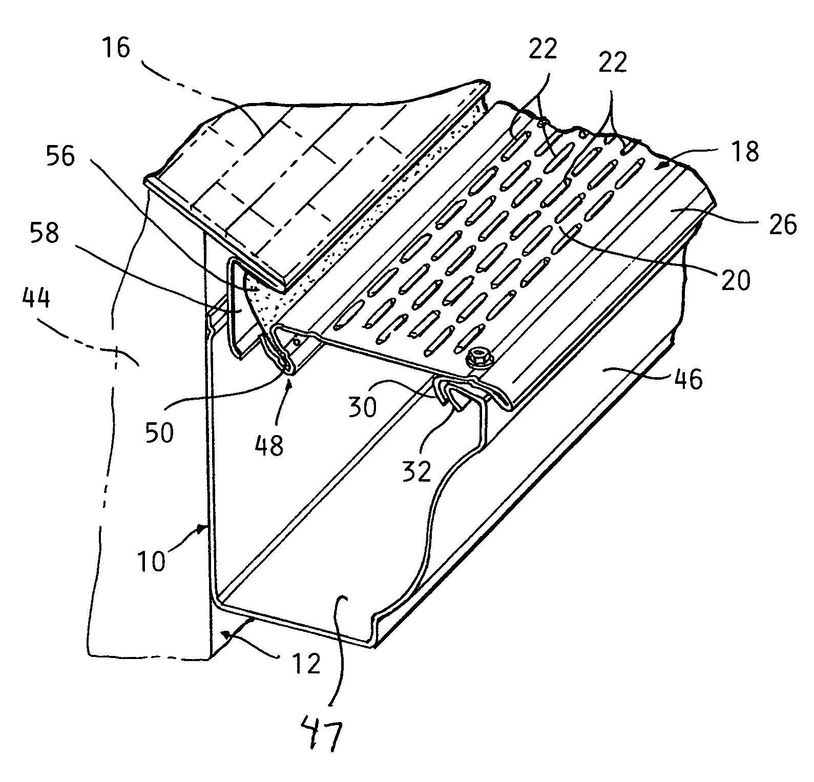
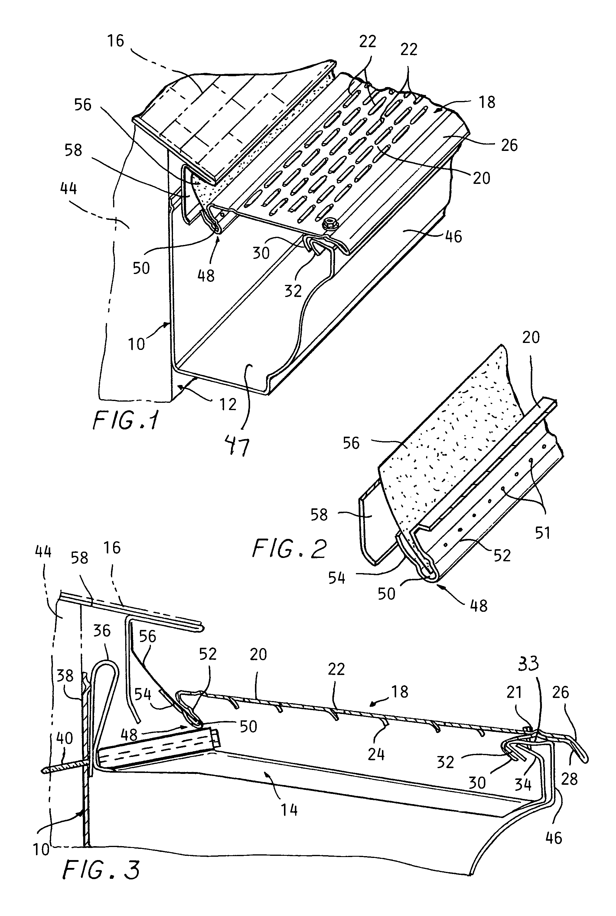
[0030]Referring to the drawings, FIG. 1 shows a roof eave gutter 10 having an outer wall 46, and inner wall 45, and a bottom wall 47 defining a gutter space for receiving rainwater drainage from the shingled roof 16. The gutter 10 is secured to a building wall 12 by a mounting bracket 14 (FIG. 3) below the shingled roof 16 so as to collect rainwater draining therefrom. A gutter cover 18 according to the present invention is installed so as to overlie the top of the gutter 10.

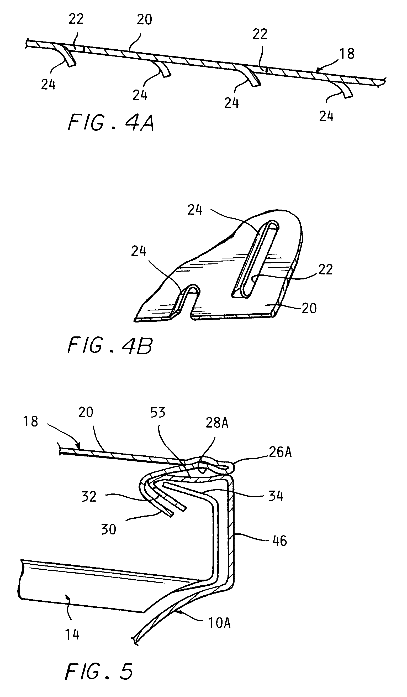
[0031]The gutter cover 18 has a generally planar main portion 20 formed with openings allowing ra...


PUM


Abstract

A gutter cover installation for covering a roof eave gutter to prevent debris from entering the gutter includes a main portion of the gutter cover formed with a pattern of openings and an outer edge of the outer side of the gutter cover projecting out and down past an outer wall of the gutter to form a diverter preventing overflow from flowing over the outer surface of the gutter outer wall and thereby avoid staining the same. The gutter cover inner side is held up by segments formed on the inner side of the cover forming a channel which projects down below the main portion and is engaged with a mounting bracket installed within the gutter to be supported thereby. An elastomeric sealing strip is inserted into the channel and projects up and back into engagement with a drip edge or fascia installed at the roof eave.

Description

CROSS REFERENCE TO RELATED APPLICATIONS[0001]This application claims the benefit of U.S. provisional application No. 61 / 192,837 filed on Sep. 22, 2008.BACKGROUND OF THE INVENTION[0002]This invention relates to covers for roof eave gutters. Debris such as twigs and leaves tends to get washed into the gutters and collect to the point of clogging the flow of rainwater. Covers or guards have come into common use which are designed to prevent the entrance of debris while allowing penetration of rainwater into the gutters thereby to reduce the problem of clogged gutters.[0003]Numerous patents have issued on such gutter covers, which generally take the form of a slotted, perforated or grid like piece of sheet metal or plastic installed over the top of the gutter.[0004]In addition, curved solid covers terminating just short of the outer edge of the gutter have been used, the curvature creating a flow of rainwater tending to project the debris over the outer edge of the gutter while the rain...

Claims


Application Information

Patent Timeline
Patent Type & Authority Patents(United States)
IPC IPC(8): E04D13/076
CPCE04D13/076
Inventor JOLY, JR., ROBERT E.CLAYPOOL, TERRY
Owner JOLY JR ROBERT E
Learn More