Apparatus for equalizing voltage across an electrical lighting system

a technology of electrical lighting and equalizing voltage, which is applied in the direction of energy-saving incandescent lamps, sustainable buildings, energy-efficient lighting, etc., can solve the problems of inconvenient wiring connection, labor and time spent on minimizing voltage drop, and excessive voltage drop or the use of extra parts, etc., to achieve easy addition of fixtures, minimizing parts, and reducing labor and time.

Inactive Publication Date: 2011-08-30
TORO CO THE
View PDF28 Cites 5 Cited by
  • Summary
  • Abstract
  • Description
  • Claims
  • Application Information

AI Technical Summary

Benefits of technology

[0010]The main object of this invention is to provide a wiring method which equalizes voltage across a lighting system while minimizing parts, labor and time spent.
[0011]It is another object of this invention to provide a wiring method which provides better wiring connections for landscape lighting, i.e., connections are not in the ground where they are exposed to oxidation and rust but are contained in an Equalizer Hub™.
[0012]The Equalizer Hub™ is a wiring manifold that distributes voltage evenly to each lamp in a given lighting system, even if one or more light fixtures fail. The Equalizer Hub™ is designed to be used in conjunction with one or more lighting fixtures, and serves as the connection point between the homerun wire from the power source, i.e. a transformer, and the fixture lead wires. The Equalizer Hub™ may be used in all applications, particularly low voltage landscape lighting, and it may be buried above or below grade. While, the Equalizer Hub™ may be used in all applications, it is most effective in low voltage situations where the amount of voltage drop in a system will have a greater effect on the light output by the individual fixtures.
[0013]Other advantages and benefits of the present invention include ease in adding fixtures to a system, easy in testing voltage, ease in troubleshooting, easy access to wire connections, and ease in moving fixtures.

Problems solved by technology

This method results in a voltage drop at each fixture and across the wiring in between.
Drawbacks of the prior art methods include excessive voltage drop or the use of extra parts, labor and time to minimize the voltage drop.
Because of the voltage drop in the above methods, lighting systems which are wired using these methods present lights that are each receiving a different voltage resulting in lights with inconsistent light output.

Method used


Image

  • Apparatus for equalizing voltage across an electrical lighting system
  • Apparatus for equalizing voltage across an electrical lighting system
  • Apparatus for equalizing voltage across an electrical lighting system

Examples


Embodiment Construction

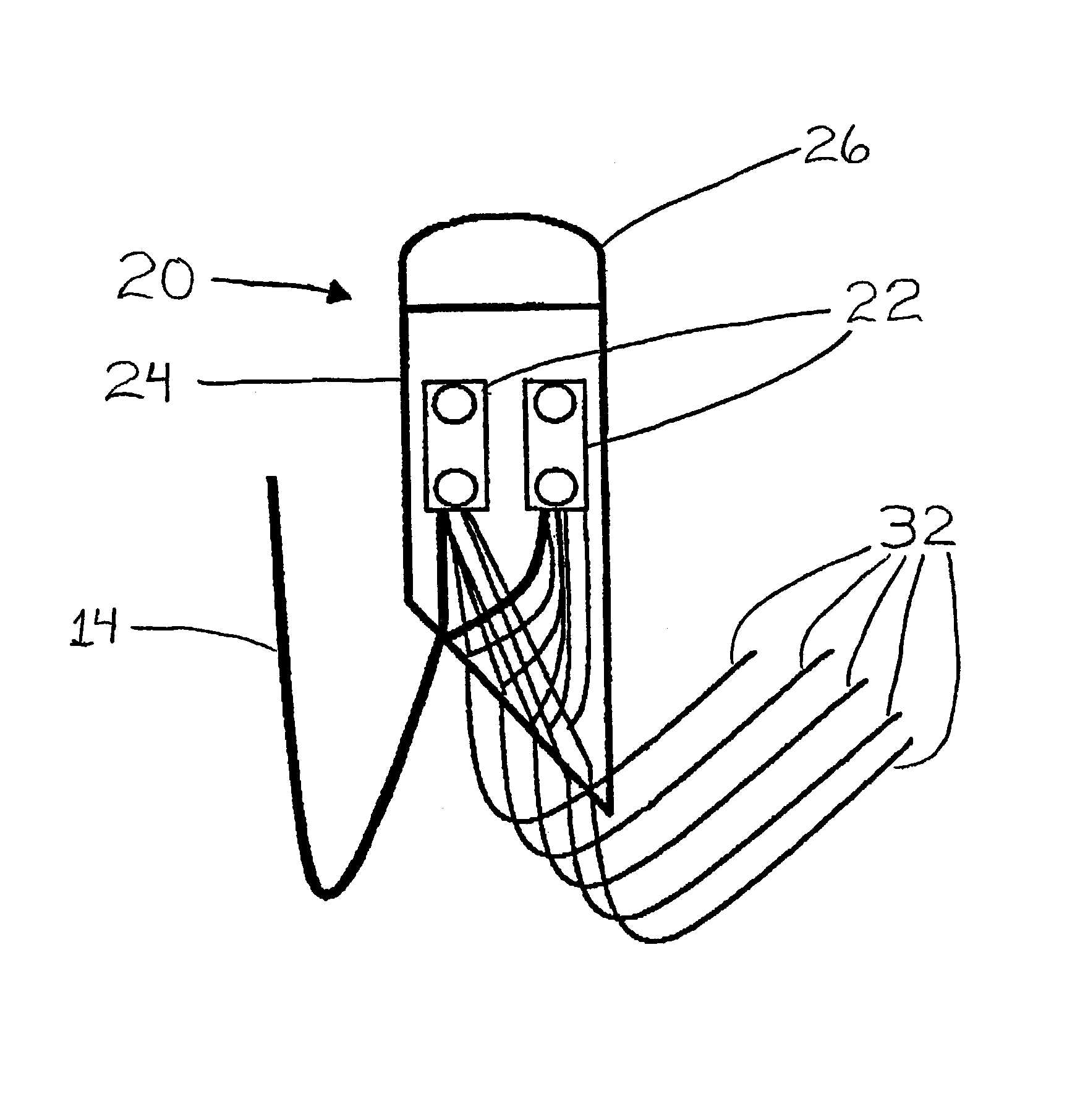
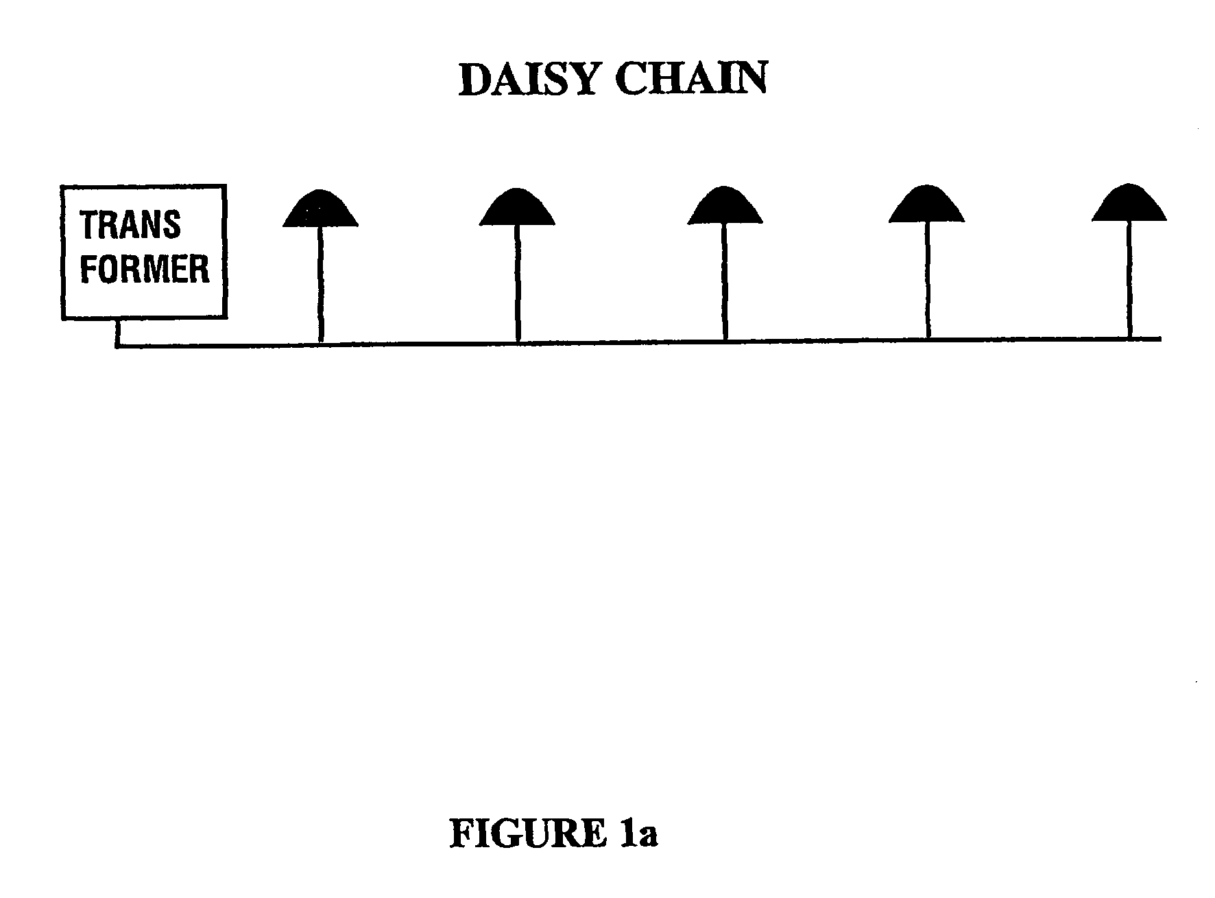
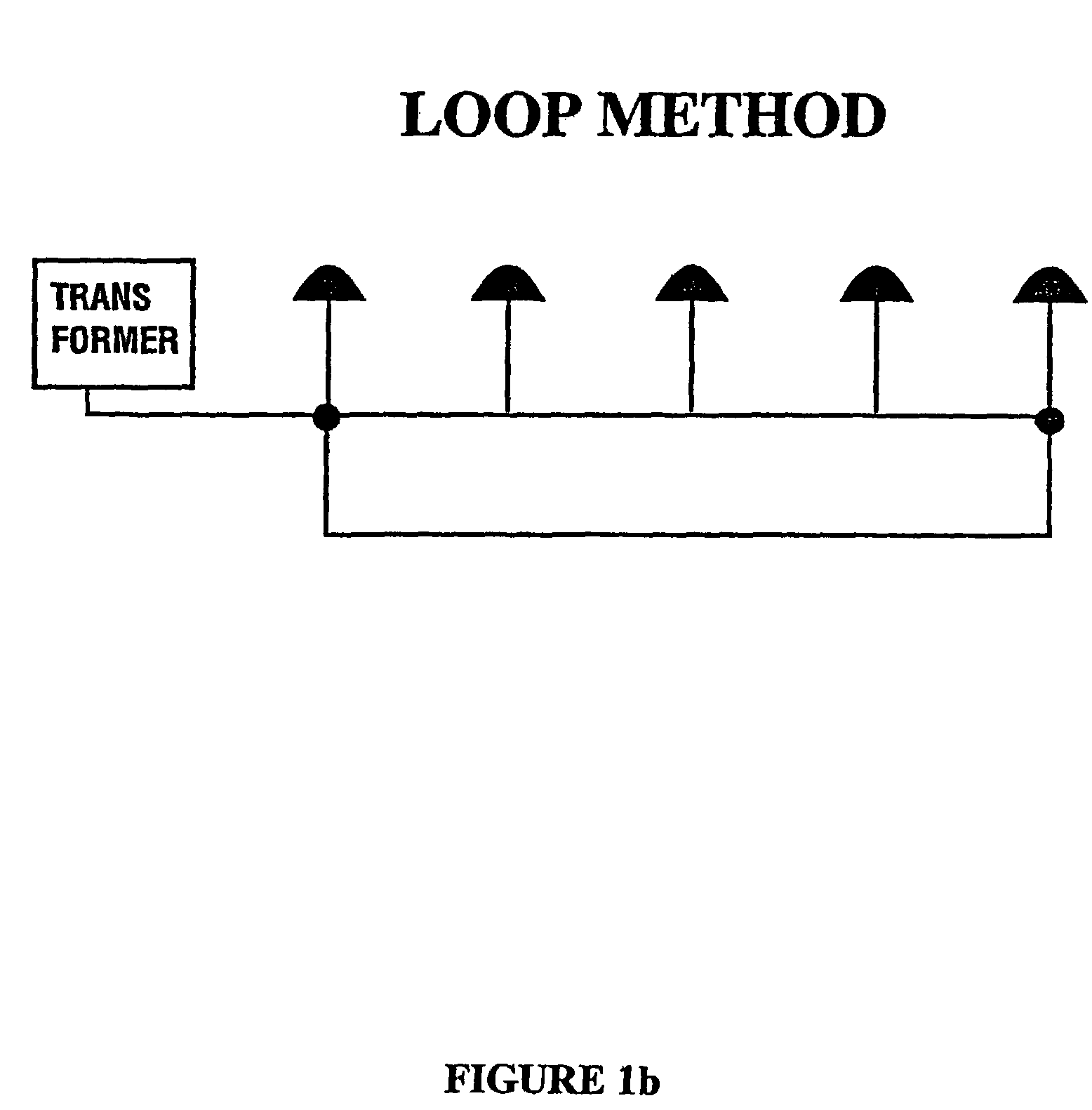
[0021]The instant invention is directed to a wiring method used for equalizing voltage delivered to each fixture in a lighting system. Primarily, the wiring method of the instant invention is intended for use in low voltage landscape lighting systems, however, the principles and methods are equally applicable to standard and high voltage systems. The benefits of this invention are more realizable in low voltage systems where the voltage drop over a given distance will cause a noticeable decrease in performance of the lighting system.

[0022]The novel designs of the present invention address the shortcomings of prior art outdoor wiring systems, namely, by providing: (i) a wiring method that saves on parts, labor and time in installation; (ii) a wiring method that results in lighting systems that do not experience a voltage drop that reduces performance; (iii) a wiring method that allows for easy addition of lighting fixtures to an existing lighting system; and (iv) a wiring method that...


PUM

PropertyMeasurementUnit
voltageaaaaaaaaaa
lengthaaaaaaaaaa
distanceaaaaaaaaaa

Abstract

An apparatus for equalizing voltage across an electrical lighting system, particularly in low voltage landscape lighting systems. The apparatus consists of a plastic cylinder having open ends and containing two or more connectors for connecting a homerun wire from a transformer to wire leads from the various light fixtures in the lighting system. The wire leads are of uniform length to ensure that each light fixture is ecu distant from the transformer.

Description

CROSS-REFERENCE TO RELATED APPLICATION[0001]This application is a divisional application, pursuant to 37 CFR 1.60, based upon and claiming the benefit of U.S. application Ser. No. 09 / 738,024, filed Dec. 14, 2000 now U.S. Pat. No. 7,699,481.STATEMENT RE: FEDERALLY SPONSORED RESEARCH AND DEVELOPMENT[0002]Not Applicable.BACKGROUND OF THE INVENTION[0003]1. Field of the Invention[0004]This invention relates to a wiring method and an apparatus used therein to equalize voltage drop across a lighting system. The method and apparatus is particularly applicable to low voltage lighting systems. As this invention was developed for use in low voltage systems, this specification will discuss the invention as applied to low voltage systems. However, the principles and teachings of this invention are applicable to both standard and high voltage systems as well.[0005]2. Description of the Related Art[0006]The prior art discloses several methods and manners for wiring lighting systems to compensate f...

Claims


Application Information

Patent Timeline
Patent Type & Authority Patents(United States)
IPC IPC(8): H01R43/00H05B39/04
CPCH05B39/044Y10T29/4913Y10T29/49121Y10T29/49117Y10T29/49128Y02B20/146Y10T29/49126Y02B20/00
Inventor MULLEN, NATE
Owner TORO CO THE
Why Eureka
Try Eureka