
Retaining feature for corrugated acoustic duct

a technology of corrugated acoustic ducts and retainers, which is applied in the direction of pipe joints, sleeves/socket joints, couplings, etc., can solve the problems of corrugated acoustic, additional materials, specialized equipment or tools for connection and installation, and increased labor and higher costs in order to make a successful connection. , to achieve the effect of minimizing materials, specialized equipment or tools, labor and cost of making a successful connection

Active Publication Date: 2006-01-05
HANON SYST
View PDF32 Cites 2 Cited by
  • Summary
  • Abstract
  • Description
  • Claims
  • Application Information

AI Technical Summary

Benefits of technology

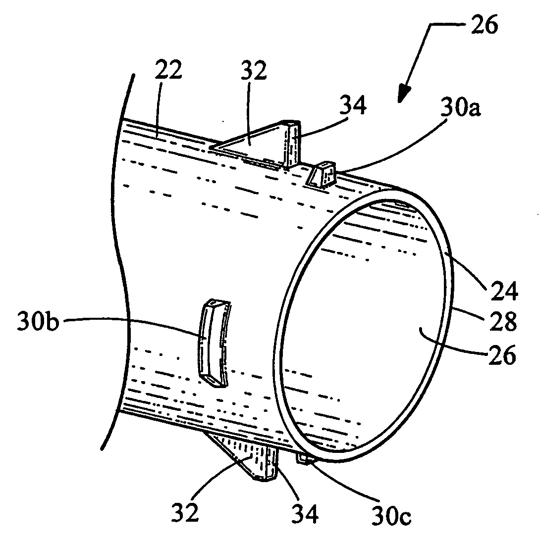
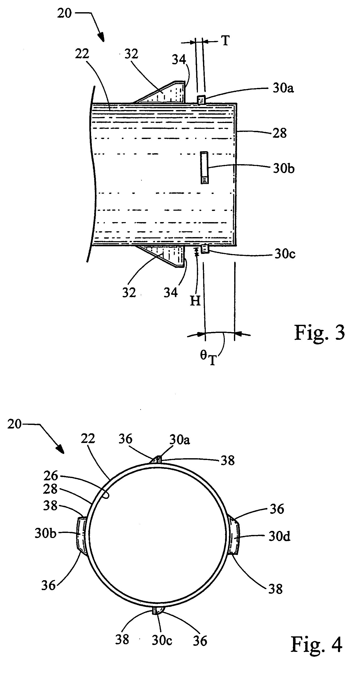
[0005] The present invention provides a retaining feature for connecting a plastic tube to a corrugated acoustic duct that accommodates variations in the undulations and thread pattern, while at the same time minimizing the materials, specialized equipment or tools, labor and cost of making a successful connection. The retaining feature includes at least one barb extending circumferentially around the exterior surface of the plastic tube. Each barb is sized and structured to engage an undulation of the corrugated duct.

Problems solved by technology

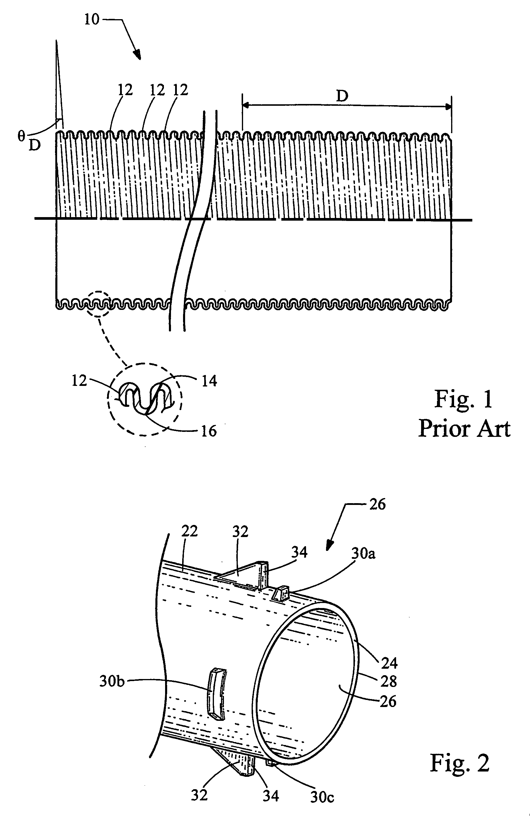
Unfortunately, such corrugated acoustic ducts are manufactured with a number of undulations that varies for a set distance D along the length of the tube.
While these traditional retention features accommodate the variance in the undulations and thread pattern, they result in additional materials, specialized equipment and tools for connection and installation, increased labor and higher cost in order to make a successful connection which does not allow water through.

Method used


Image

  • Retaining feature for corrugated acoustic duct
  • Retaining feature for corrugated acoustic duct
  • Retaining feature for corrugated acoustic duct

Examples


Embodiment Construction

[0013] Turning now to the figures, FIGS. 2, 3 and 4 depict various views of a retaining feature 20 formed on a plastic tube 22 in accordance with the teachings of the present invention. The retaining feature 20 is designed to provide a successful connection of the plastic tube 22 to the corrugated acoustic duct 10 depicted in FIG. 1. The plastic tube 22 generally includes a free end 28, and is cylindrical in nature defined by an inner surface 26 and an outer surface 28. The plastic tube 22 is sized to fit inside the corrugated duct 10, and thus the outer diameter of the tube 22 is sized to fit within the inner diameter of the corrugated duct 10 defined by the grooves 16 of the undulations 12. It will be recognized by those skilled in the art that the plastic tube 22 could be designed to fit over the corrugated duct 10, and thus would have an inner diameter that is greater than the outer diameter of the duct 10. Likewise, and thus the retaining feature 20 would be formed on the inner...


PUM


Abstract

A retaining feature is provided for connecting a plastic tube to a corrugated acoustic duct. The retaining feature accommodates variations in the undulations and thread pattern of the corrugated duct, while at the same time minimizing the materials, specialized equipment or tools, labor and cost of making a successful connection. The retaining feature includes at least one barb extending circumferentially around the exterior surface of the plastic tube. Each barb is sized and structured to engage an undulation of the corrugated duct.

Description

FIELD OF THE INVENTION [0001] The present invention relates generally to corrugated acoustic ducts commonly found in air routing systems in automobiles, and more particularly relates to the retaining features for connecting a plastic tube to the corrugated acoustic duct. BACKGROUND OF THE INVENTION [0002] Corrugated acoustic ducts are commonly used in the air handling systems of automobiles. Such corrugated ducts are formed of a series of undulations creating a spiral pattern much like the thread on a fastener. A corrugation is comprised of multiple undulations, and an undulation consists of one full ridge and one full groove which lie parallel to one another. This structure can clearly be seen in FIG. 1, which depicts a corrugated acoustic duct 10 having a series of undulations 12 defined by alternating ridges and 14 and grooves 16. The undulations are disposed at a helical angle θD. For example, a Sonoflex™ acoustic duct is manufactured by West Akron, 571 Kennedy Rd., Akron, Ohio....

Claims


Application Information

Patent Timeline
IPC IPC(8): F16L21/00
CPCY10S285/903F16L25/0045
Inventor PETERSON, CHARLES BRYANHAMBY, STEPHEN JOSEPHSHAH, MILAP KANU
Owner HANON SYST
Learn More