Transmission device for a door lock

a technology for transmitting devices and door locks, applied in mechanical control devices, keyhole guards, instruments, etc., can solve problems such as security issues affecting key cards or biometric data, and cannot open electronically controlled locks, so as to improve security and versatility of locks

Active Publication Date: 2011-08-30
TAIWAN FU HSING INDAL
View PDF15 Cites 1 Cited by
  • Summary
  • Abstract
  • Description
  • Claims
  • Application Information

AI Technical Summary

Benefits of technology

[0007]The main objective of the invention is to provide a transmission device with a solenoid switch for a door lock that can be opened using a corresponding key or an electronic actuator to improve security and versatility of the lock. The transmission device comprises a solenoid switch, a driven device and a linkage assembly. The solenoid switch comprises a solenoid core, a guide tube, an sleeve and a clutch cap. The solenoid core has a receiving hole defined in the solenoid core and a solenoid coil wound around the solenoid core. The guide tube is mounted in the receiving hole in the solenoid core and has an axial hole and a connecting end. The axial hole is defined through the guide tube. The connecting end is formed on one end of the guide tube and extends out of the receiving hole in the solenoid core. The sleeve is mounted slidably in the receiving hole in the solenoid core and around the guide tube and has at least one engaging tab formed on and protruding from the sleeve at one end facing the connecting end of the guide tube. The clutch cap is mounted around the connecting end of the guide tube and has at least one engaging notch selectively and detachably engaging respectively with corresponding engaging tabs on the sleeve. The driven device is securely connected to the solenoid switch. The linkage assembly is connected to the solenoid switch and comprises an outer linkage, an inner linkage and at least one spring. The outer linkage is connected to the clutch cap of the solenoid switch. The inner linkage is connected to the outer linkage and the driven device. The at least one spring is connected between the inner linkage and the driven device. Therefore, the door lock may be locked by a key or internal mechanism moving the linkage assembly away from engaging the handle. Then actuating the solenoid coil allows the linkage assembly to engage the handle and allows the door lock to be opened without the corresponding key.

Problems solved by technology

However, a key controlled lock and an electronically controlled lock are individual so a key cannot open the electronically controlled lock.
Therefore, implementing electronically controlled locks means a building manager or the like who may be required to open doors in emergencies must have such access to all locks in a building thereby causing security issues regarding their key card or biometric data.

Method used


Image

  • Transmission device for a door lock
  • Transmission device for a door lock
  • Transmission device for a door lock

Examples


second embodiment

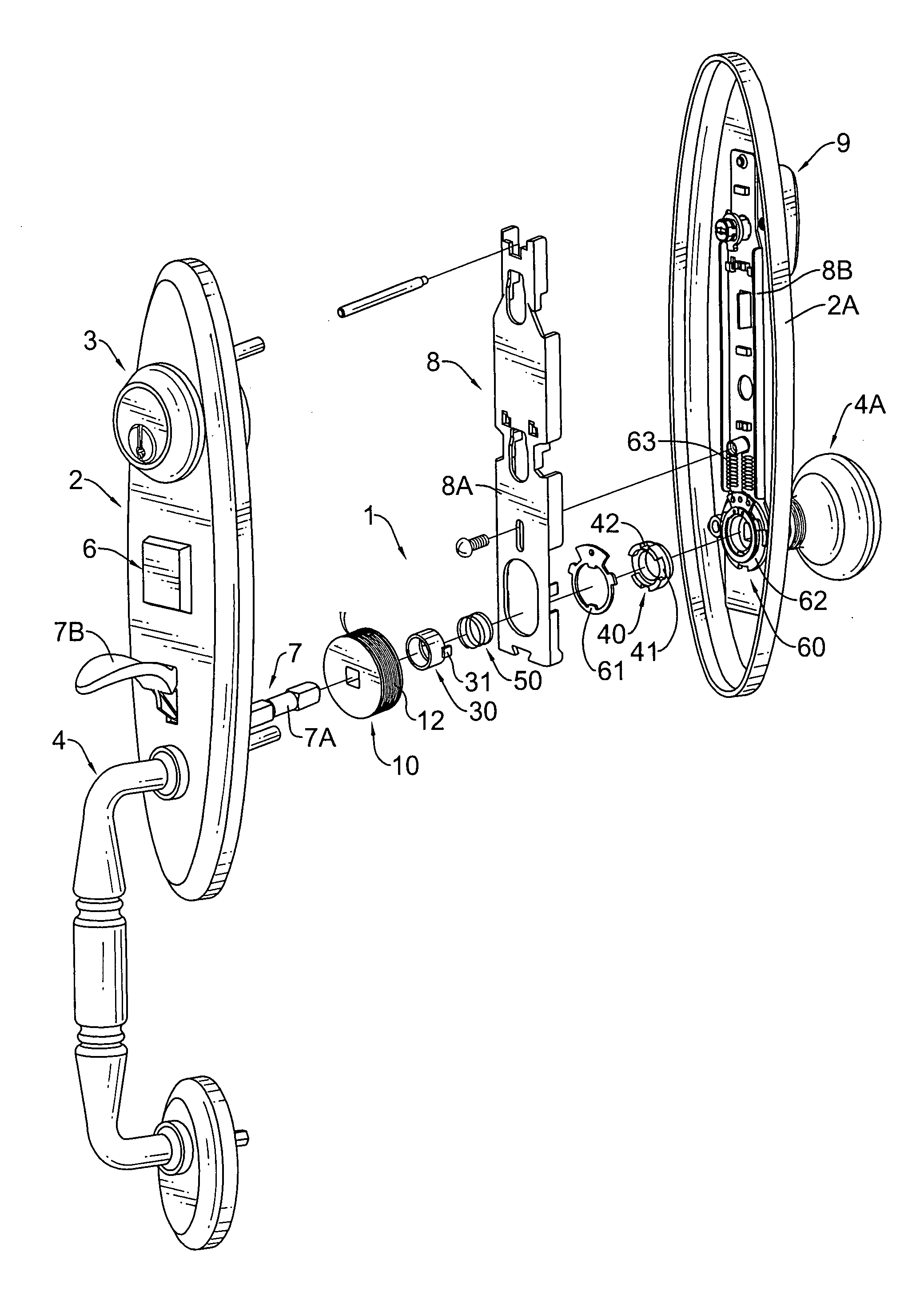
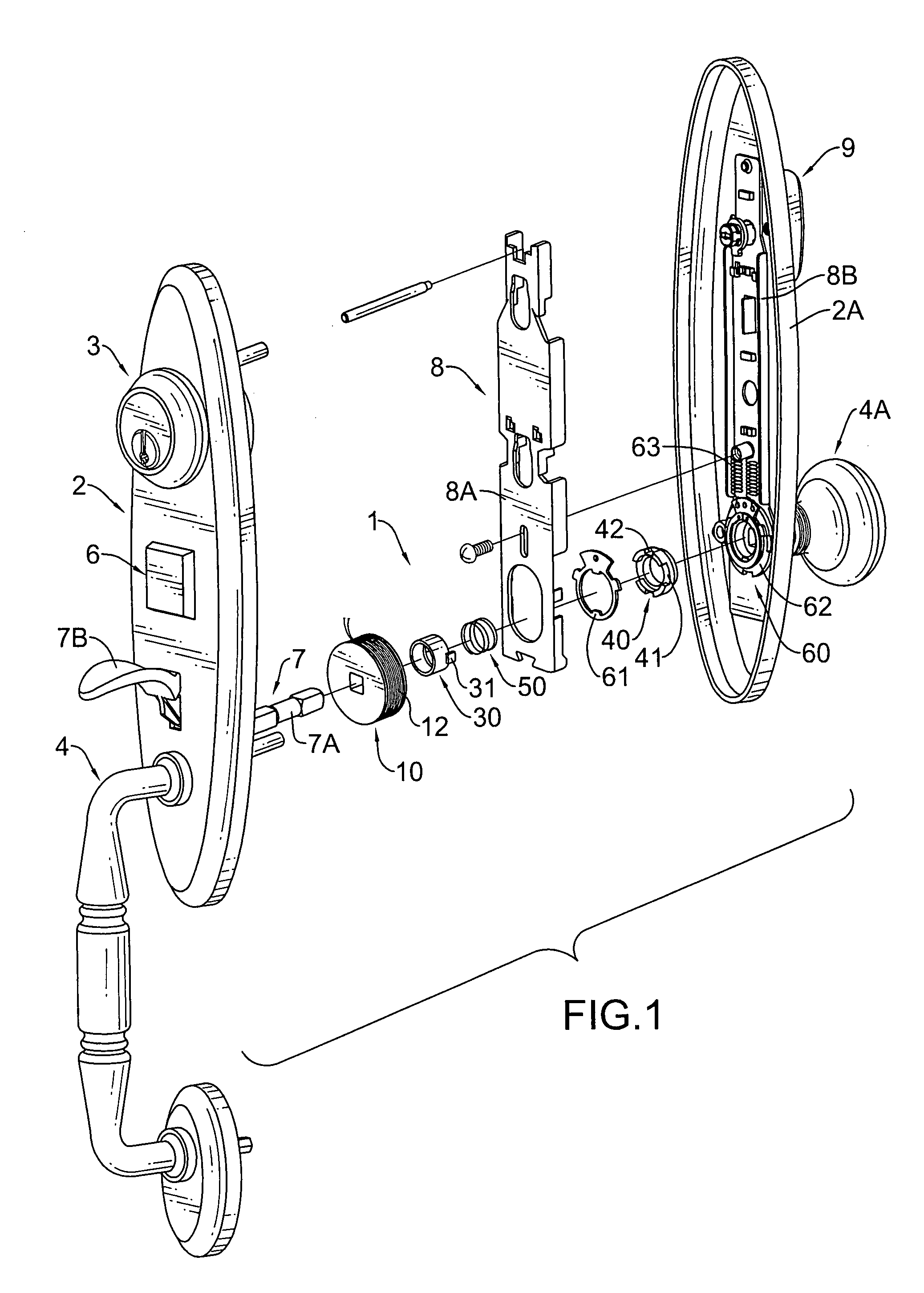
[0029]In the second embodiment, the sleeve (30A) further has an inner surface and at least one guiding protrusion (32) formed on the inner surface of the sleeve (30A) at an end opposite to the at least one engaging tab (31) and is mounted slidably in and engages with a corresponding guiding channel (26) in the guide tube (20A). With the engagements between the protrusions (32) and the channels (26), the sleeve (30A) will be rotated with the guide tube (20A).

[0030]The clutch cap (40) is mounted around the connecting end (22) of the guide tube (20,20A) and has at least one engaging notch (41) and an optional driving notch (42). The engaging notch (41) selectively and detachably engages respectively a corresponding engaging tab (31) on the sleeve (30, 30A) and has a width larger than that of the corresponding engaging tab (31) on the sleeve (30,30A).

first embodiment

[0031]In the first embodiment, the guide tube (20) further comprises an annular fastening groove (28) and a fastener (29). The annular fastening groove (28) is defined around the connecting end (22) of the guide tube (20). The fastening element (29) may be a C-ring, is mounted on the connecting end (22), may be in the fastening groove (28) and abuts the clutch cap (40) to hold the clutch cap (40) on the connecting end (22) of the guide tube (20).

[0032]In the second embodiment, the annular flange (23) on the guide tube (20A) abuts the clutch cap (40) to hold the clutch cap (40) adjacent to the connecting end (22) of the guide tube (20A).

[0033]Each driving notch (42) is defined in the clutch cap (40).

[0034]The resilient element (50) is mounted around the guide tube (20,20A), may be a spring and presses the sleeve (30,30A) away from the clutch cap (40). The driven device (60) is securely connected to the clutch cap (42) of the solenoid switch and comprises an outer ring (61) and an inn...


PUM


Abstract

A transmission device for a door lock has a solenoid switch, a driven device and a linkage assembly. The solenoid switch has a solenoid core, a guide tube, a sleeve and a clutch cap. The guide tube is mounted in the solenoid core and has a connecting end. The connecting end is formed on one end of the guide tube and protrudes out of the solenoid core. The sleeve is mounted slidably in the solenoid core and around the guide tube and has at least one engaging tab formed on and protruding from the sleeve at one end adjacent to the connecting end of the guide tube. The clutch cap is mounted around the connecting end of the guide tube and has at least one engaging notch selectively and detachably engaging respectively with a corresponding engaging tab on the sleeve.

Description

BACKGROUND OF THE INVENTION[0001]1. Field of the Invention[0002]The present invention relates to a transmission device, and more particularly to a transmission device for a door lock having a solenoid switch to selectively disengage a locking mechanism.[0003]2. Description of Related Art[0004]A traditional door lock is opened using a corresponding key, however advances in technology allow the key to be replaced by an electronic actuator, such as a finger print identifier, a chip detecting sensor and the like; having the advantages of matching biometric, magnetic or electronic data being required to open the door lock. However, a key controlled lock and an electronically controlled lock are individual so a key cannot open the electronically controlled lock.[0005]Therefore, implementing electronically controlled locks means a building manager or the like who may be required to open doors in emergencies must have such access to all locks in a building thereby causing security issues re...

Claims


Application Information

Patent Timeline
Patent Type & Authority Patents(United States)
IPC IPC(8): E05B47/00
CPCE05B47/068E05B47/0004Y10T70/5226Y10T70/5155Y10T70/7107Y10T70/7062Y10T70/5416Y10T70/7102Y10T70/5805
Inventor HUANG, CHAO-MINGCHEN, CHI-MING
Owner TAIWAN FU HSING INDAL
Why Eureka
Try Eureka