Pneumatic tire with tread having fine grooves

a technology of pneumatic tires and grooves, which is applied in the field of pneumatic tires, can solve the problems of difficult general drivers to determine whether or not the tire can maximize the potential, the tread surface wear of the pneumatic tire is not uniform over the entire ground contact surface, and the pneumatic tire does not sufficiently maximize the potential. to achieve the effect of maximizing the potential

Inactive Publication Date: 2011-08-30
THE YOKOHAMA RUBBER CO LTD
View PDF17 Cites 4 Cited by
  • Summary
  • Abstract
  • Description
  • Claims
  • Application Information

AI Technical Summary

Benefits of technology

An object of the present invention is to provide a pneumatic tire that includes fine grooves formed in the tread surface for compensating for the lack of the initial performance, and that makes it possible to easily see whether or not the tire can maximize the potential.
According to the pneumatic tire of the present invention, the inclined directions of the fine grooves relative to the circumferential direction of the tire are set reverse to each other on the left and right sides of the equator of the tire. Accordingly, it is possible to make frictional forces acting on the ground-contacting surface uniform with respect to the land portions on the two sides of the equator of the tire, and to thus cause the fine grooves to be uniformly worn. As a result, the driver can visually and easily determine whether or not the tire can maximize the potential.

Problems solved by technology

In general, at the beginning of use of a pneumatic tire, the pneumatic tire does not sufficiently maximize the potential.
However, the progression of wear of the tread surface of a pneumatic tire is not uniform over the entire ground-contacting surface.
For this reason, even when the above-described shallow fine grooves are provided, it is difficult for general drivers to determine whether or not the tire can maximize the potential.Patent Document 1: Japanese patent application Kokai publication No. 2004-34903

Method used


Image

  • Pneumatic tire with tread having fine grooves
  • Pneumatic tire with tread having fine grooves

Examples


embodiment 1

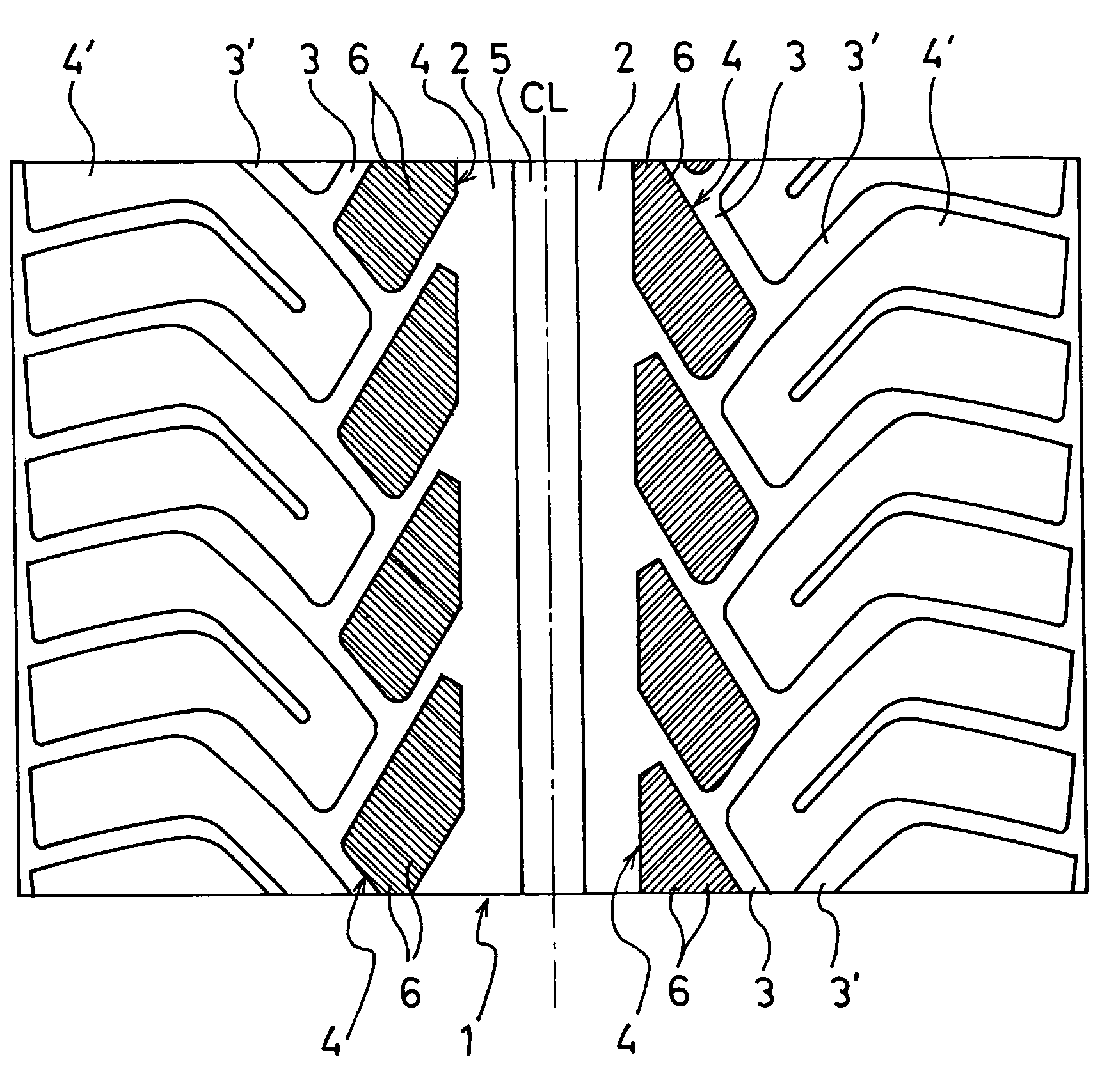
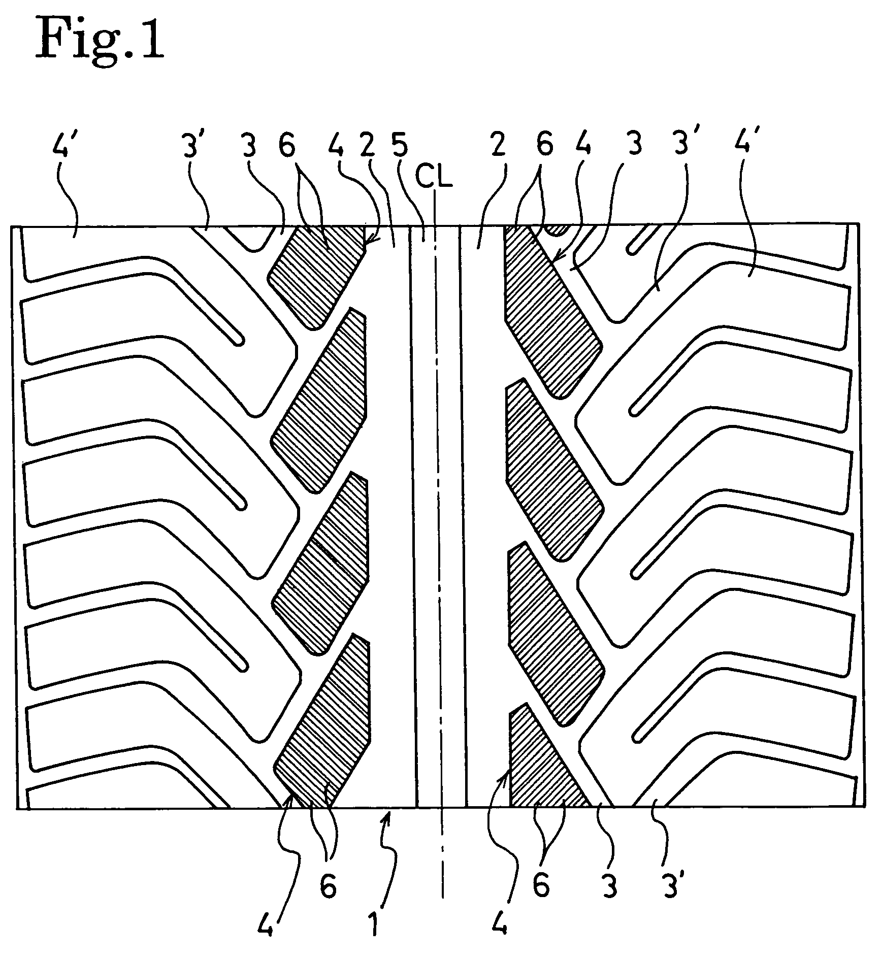
A pneumatic tire with the following configuration was prepared. Specifically, fine grooves were formed in the entire ground-contacting region of land portions in the tread part to be symmetrical about the equator of the tire, while the land portions had a tread pattern symmetrical about the equator of the tire. The inclination angle of each fine groove relative to the circumferential direction of the tire was 50°. The depth and the width of each fine groove were 0.4 mm and 0.4 mm, respectively. The pitch of the fine grooves was 1.3 mm.

The prepared pneumatic tire was broken in, in the above-described manner, to be evaluated in terms of the state of wear of the land portions of the tread part. The result of the evaluation is shown in Table 1.

TABLE 1EmbodimentEmbodimentEmbodimentEmbodimentEmbodimentEmbodimentEmbodimentComparativeComparative1234567Example 1Example 2Pattern of LandSymmetricalSymmetricalSymmetricalSymmetricalSymmetricalSymmetricalDirectionalSymmetricalSymmetricalPortionsa...

embodiment 2

A pneumatic tire was prepared in the same manner as in the case of Embodiment 1, except the following configuration. Specifically, the pneumatic tire of Embodiment 2 had the tread part with a shape symmetrical about the equator of the tire. Concurrently, land portions were arranged on the left and right sides of the equator to be displaced from each other in the circumferential direction by approximately 25% of the pitch in the tread part. Then, the same break-in run and evaluation as those in the case of Embodiment 1 were performed on the pneumatic tire of Embodiment 2. The result of the evaluation is shown in Table 1. It was demonstrated that the pneumatic tire of Embodiment 2 was the same as that of Embodiment 1 in terms of, the uniformity of wear of the land portions of the tread part, the visibility of the wear-out of the fine grooves, and the like. Moreover, in addition, a reduction in running noise was obtained.

embodiment 3

A pneumatic tire was prepared in the same manner as in the case of Embodiment 1, except the following configuration. Specifically, the pneumatic tire of Embodiment 3 had the same shape of the tread part as that of Embodiment 2. Concurrently, fine grooves were formed to be inclined, at 45° on the left side (on the inner side at the time when the tire was installed in the vehicle) of the equator of the tire, and at 60° on the right side (on the outer side at the time when the tire was installed in the vehicle) thereof. Then, the same break-in run and evaluation as those in the case of Embodiment 1 were performed on the pneumatic tire of Embodiment 3. The result of the evaluation is shown in Table 1.


PUM


Abstract

Disclosed is a pneumatic tire including a plurality of land portions and a plurality of fine grooves. The plurality of land portions are formed of blocks and a rib, and are defined in a tread part of the pneumatic tire. The fine grooves with a depth of 0.1 mm to 0.8 mm, a width of 0.1 mm to 0.8 mm and a pitch of 0.5 mm to 2.0 mm are formed in the tread surface of each of the land portions to be inclined at an angle of 42° to 60° relative to the circumferential direction of the tire. The inclined directions of the fine grooves relative to the circumferential direction of the tire are reverse to each other on the left and right sides of the equator of the tire.

Description

TECHNICAL FIELDThe present invention relates to a pneumatic tire. Specifically, the present invention relates to a pneumatic tire that includes fine grooves formed in the tread surface for compensating for the lack of the initial performance of the tire, and that makes it possible to easily see whether or not the tire can maximize the potential from the peeling off of the tread surface.BACKGROUND ARTIn general, at the beginning of use of a pneumatic tire, the pneumatic tire does not sufficiently maximize the potential. This is because a mold release lubricant, which has been applied to the mold surface for the purpose of improving the releasability of the pneumatic tire from the mold in a curing process, remains on the tread surface of the pneumatic tire. Accordingly, break-in of the pneumatic tire for a certain distance is necessary to wear off the tread surface of the pneumatic tire so that the genuine tread rubber can be exposed to the outside. After the break-in, the pneumatic t...

Claims


Application Information

Patent Timeline
Patent Type & Authority Patents(United States)
IPC IPC(8): B60C11/12
CPCB60C11/0302B60C11/12B60C2011/1231Y10S152/03Y10S152/904B60C2011/0388
Inventor EBIKO, MASAHIRO
Owner THE YOKOHAMA RUBBER CO LTD
Why Eureka
Try Eureka