Surgical instrument design

a surgical instrument and design technology, applied in the field of surgical instrument design, can solve problems such as tissue damage and stress at the incision

Active Publication Date: 2011-08-30
AURIS HEALTH INC
View PDF233 Cites 1059 Cited by
  • Summary
  • Abstract
  • Description
  • Claims
  • Application Information

AI Technical Summary

Problems solved by technology

Such pivoting causes stress at the incision and can damage tissue.

Method used


Image

  • Surgical instrument design
  • Surgical instrument design
  • Surgical instrument design

Examples


Embodiment Construction

A description of preferred embodiments of the invention follows.

The present invention, is related to co-pending U.S. patent application Ser. No. 10 / 299,588 filed Nov. 18, 2002; co-pending U.S. patent application Ser. No. 10 / 012,845 filed on Nov. 16, 2001 and published as U.S. Publication No. 2002 / 0128633 on Sep. 12, 2002 and co-pending U.S. patent application Ser. No. 10 / 302,804 filed Nov. 21, 2002, the entire teachings of which are incorporated herein by reference.

Any reference to figure numbers herein pertains to the above list of drawings that are attached hereto. Reference to any other figure numbers will be by identification as to the co-pending application in which the figure appears.

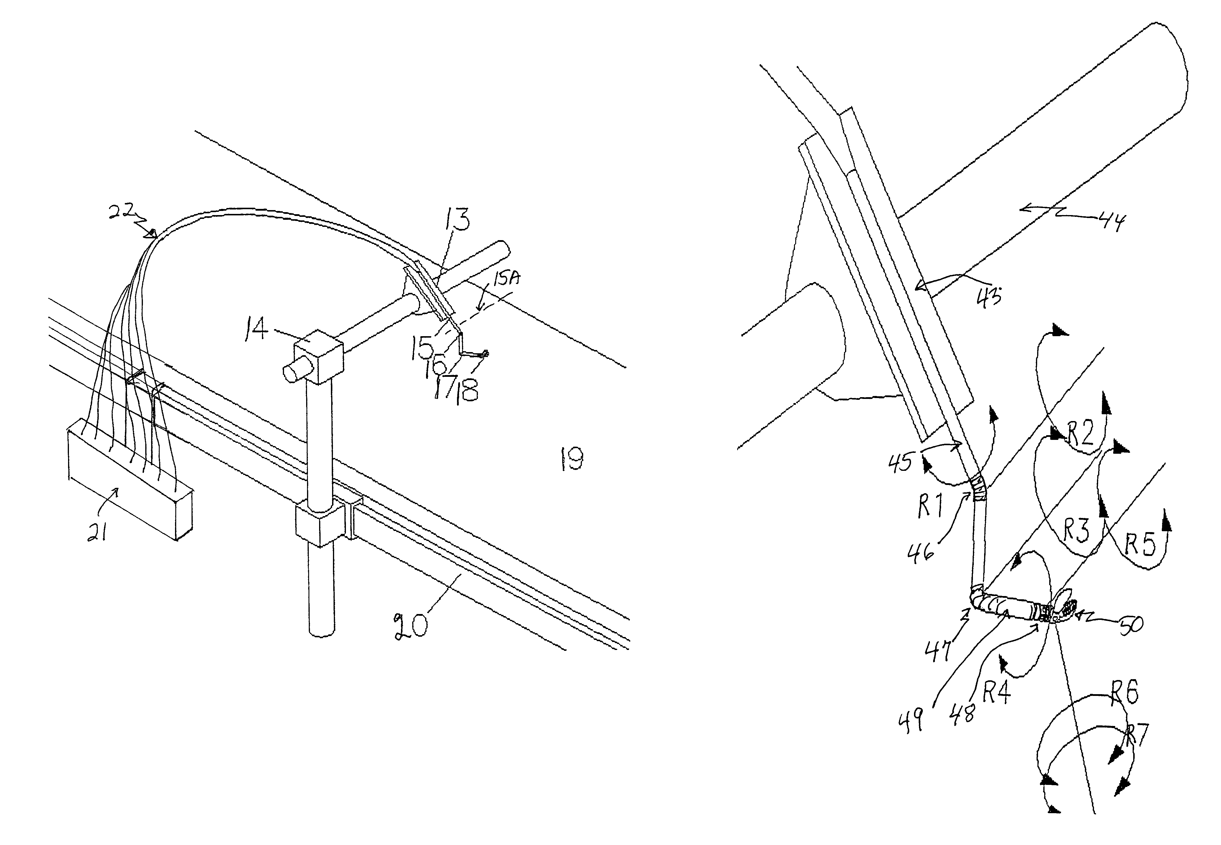
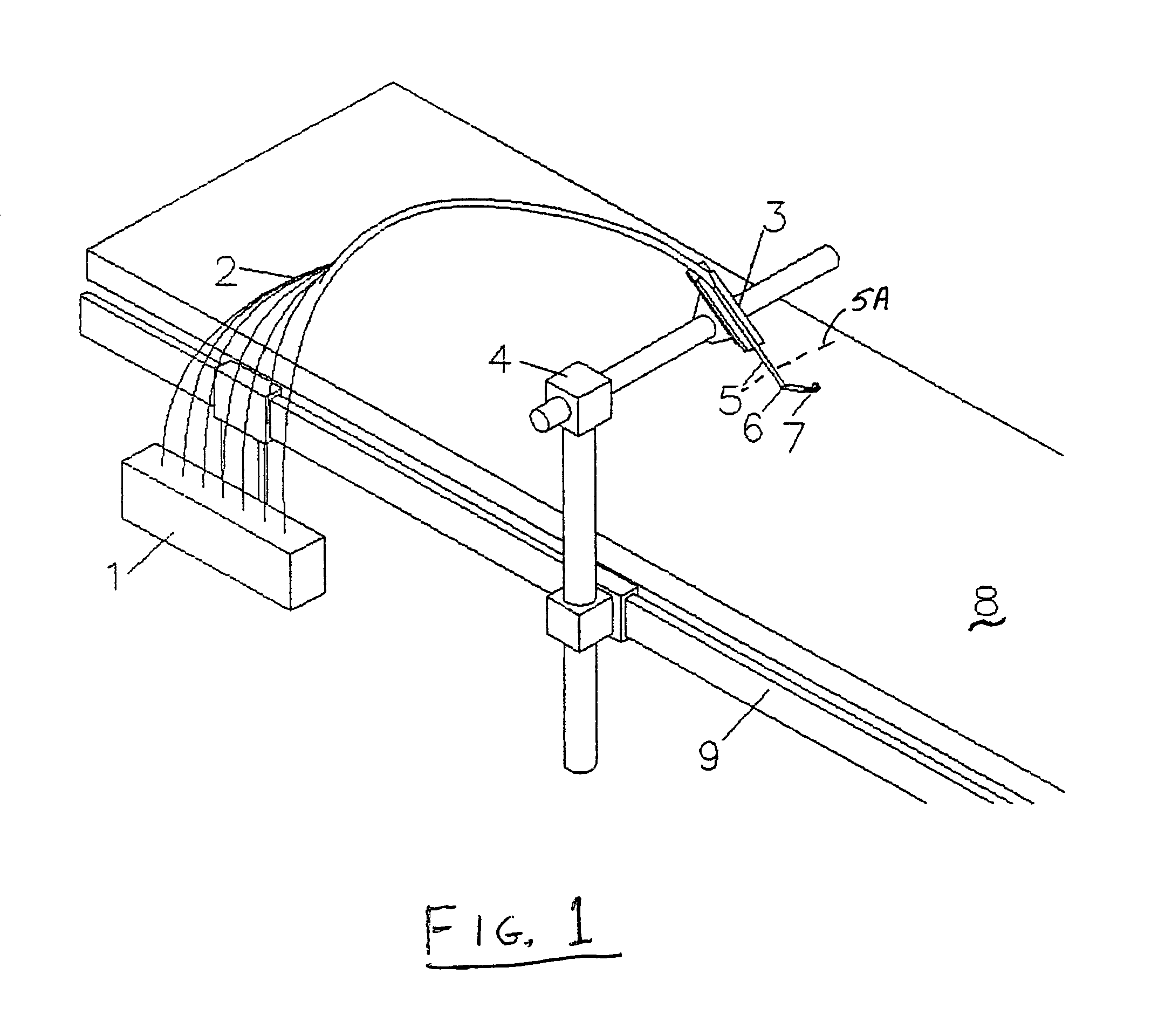
FIG. 1 is a perspective view of one embodiment of the invention using an internal wrist and elbow. This view depicts a motor array or pack 1 mounted to a surgical table 8. The motor array may be supported from the table rail 9, and is usually disposed outside the sterile field. A plurality of cabl...


PUM


Abstract

A surgical instrument system having an instrument member or shaft with a distal portion positionable through an incision of a patient to an internal site and for operation by a surgeon from outside the patient. A tool is carried at the distal end of the instrument shaft controlled by the surgeon in performing a procedure at an operative site of the patient. At least first and second turnable members are spacedly disposed along the instrument shaft distal portion, both disposed within the internal site, and each controlled from outside the patient for providing at least respective first and second degrees of freedom of control of the tool. The turnable members may be either a pivot joint or a bendable section.

Description

BACKGROUND OF THE INVENTIONJust as the unique curved guide tube concepts represent an improvement over past systems, particularly ones using a “center-of-rotation” of the instrument at the incision, the concepts set forth herein represent still other improvements by further minimizing the rotation or pivoting at the incision. In some embodiments described herein only rotation occurs at the incision and no pivoting. Such pivoting causes stress at the incision and can damage tissue. In other embodiments described herein neither pivoting, rotation nor translation occur at the incision.SUMMARY OF THE INVENTIONThe systems that are described herein use a novel combination of internal (of the patient) degrees-of-freedom to achieve a fully articulated telesurgical instrument system. Unlike traditional telesurgical systems, which use complex and heavy robotic arm assemblies to simulate human movement, the systems described herein preferably use a combination of internal and external motions,...

Claims


Application Information

Patent Timeline
Patent Type & Authority Patents(United States)
IPC IPC(8): A61B17/29A61B17/00A61B17/28A61B19/00
CPCA61B19/22A61B19/26A61B2017/00398A61B2017/2927A61B2017/2929A61B2019/2242A61B34/70A61B34/71A61B90/50
Inventor BROCK, DAVID L.LEE, WOOJIN
Owner AURIS HEALTH INC
Why Eureka
Try Eureka